
A vacuum lifter does not have one universal response to a power failure. A crane-suspended vacuum attachment may retain suction temporarily while the crane supports the frame. A vacuum tube lifter uses vacuum for both gripping and lifting, so its protection can involve a controlled descent. A pneumatic manipulator may protect the lifting arm while its suction tool needs a separate assessment.
The useful question is therefore not just “Will it hold?” Ask what stops, what retains the workpiece, what can still move and how the load reaches a safe support. The answer must match the supplied machine, end tool and material. None of the examples below establishes a universal holding time.
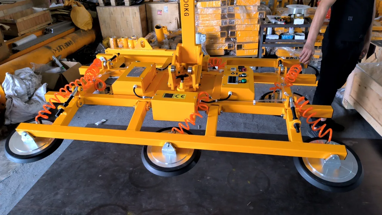
Start with the equipment, not the word “vacuum”
Vacuum attachment on a crane or hoist
The attachment grips the workpiece; the hoist carries the attachment and load. Vacuum retention and the hoist's ability to hold or lower are separate questions.Vacuum tube lifter
The lifting tube and suction head share the vacuum supply. Retaining vacuum delays its loss, but the load may descend rather than remain at the same height.Pneumatic rigid-arm or wire-rope manipulator with a suction tool
Compressed air can serve lifting, controls and vacuum generation. Protection of vertical motion, rotation and workpiece grip must be identified separately.Battery-powered glass handling equipment
A building power cut is different from loss of the machine's battery supply. Travel, hydraulic movement, vacuum gripping and warning circuits may have different dependencies.
First identify the pump or blower, the lifting mechanism, the fitted suction tool and the source of each warning. A lifting eye, articulated arm or battery enclosure is useful for identifying the arrangement, but does not reveal the internal safety circuit.
Vacuum attachments: a reserve, a valve and an alarm do different jobs
A vacuum reservoir adds evacuated volume to the connected suction circuit. A non-return valve limits reverse flow through the part of the circuit where it is installed. An alarm tells the operator that a monitored condition has crossed a limit. These functions complement one another; none can replace a sound seal between the pads and the workpiece.
Protection or indication | Purpose and limit |
|---|---|
Vacuum reservoir | Provides a reserve of evacuated volume when the source stops. Air entering through the load, pads, hoses or valves still reduces vacuum. It is not a permanent substitute for the pump. |
Non-return valve | Limits reverse flow across that valve. It cannot close a torn pad or a leak elsewhere on the load side of the circuit. |
Vacuum gauge | Shows pressure at its connected measuring point. Check which pad circuit it represents; a reading does not describe every isolated branch automatically. |
Low-vacuum or supply-failure alarm | Warns of the monitored fault. It does not create suction or mechanically catch the load. Its power supply and response to a total supply failure matter. |
Separate vacuum circuits | Can separate failure paths when designed and rated to do so. Several pads or two gauges alone do not establish independent protection or a remaining load rating. |
Release interlock or guarded release control | Helps prevent unintended release. It does not compensate for leakage, unsuitable material or a failed vacuum source. |
For a concrete example, the RDS hydraulic-tilting attachment instructions describe a vacuum reservoir for temporary retention when the source fails, a vacuum gauge, pressure-switch control of the pump and an audible/visual warning for low vacuum or sudden power loss. The same component description identifies a self-locking manual suction/release valve where that valve is fitted. These are distinct functions on that configuration, not a promise that every RDS variant or every glass lifter has the same circuit.
Before selecting an attachment, have the supplied circuit and manual identify the reservoir, non-return valve, monitored point and release control. Where independent circuits are offered, obtain the permitted load and recovery procedure for the actual failure condition. Do not calculate a remaining capacity by counting the pads that appear to remain connected.
A stopped pump is not the same fault as a lost seal
Consider an attachment on clean, nonporous glass. If its pump stops while the connected circuit remains sealed, a reservoir and appropriate valves can delay vacuum decay. Now consider the same attachment with a cut seal, a hose pulled from a fitting or a pad partly over an edge. Air has a new route into the suction circuit. Stopping reverse flow towards the pump does not close that route.
A porous board or bag presents a different problem again: air can pass through the material even when the pad sits correctly. The normal vacuum source may be selected to handle that continuous airflow. Losing the source removes that contribution. A retention result obtained on smooth glass cannot be transferred to a porous workpiece.
This is why surface, orientation, pad arrangement and failure location belong in a protection assessment. Use the vacuum source and surface selection guide to separate leakage through a material from the flow needed to evacuate a sealed volume. If the fault is already occurring during use, follow the suction-loss diagnostic guide after the load is safely supported.
Vacuum tube lifters: delayed vacuum loss can mean descent
On a vacuum tube lifter, the vacuum that holds the load also acts in the lifting tube. As vacuum decreases, the tube's lifting action changes. “The load has not detached” and “the load stays at its original height” are therefore different observations.
The Easytech tube-lifter instructions describe a one-way valve at the rotating-head inlet that delays vacuum loss after a power failure. Their emergency section describes using the specified lifting-control position so that residual vacuum allows the lifting tube and load to descend more slowly. This is a machine-specific response requiring an intact, suitable system and a trained operator; it is not a guarantee that a damaged tube or leaking head will behave the same way.
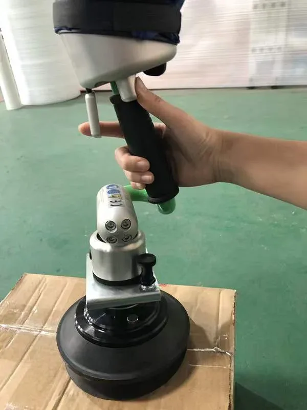
Confirm the emergency control position on the installed head during training. A rocker lever, a rotating control and a hover-adjustment screw are not interchangeable. Do not use a photograph to infer which direction to turn a control, and do not adjust the loaded-hover setting as an improvised response to a power cut.
The receiving surface and the clear area beneath the load are part of the operating plan. A device that descends needs a suitable place to set the workpiece down. Keep people out of the load area and follow the supplied emergency procedure; if safe placement is not possible, move clear and keep others clear. Do not reach underneath to catch or support the load.
For a tube lifter that will not pick up, hover or travel normally while its source is running, use the separate tube-lifter diagnostic guide. A power-loss response does not explain every ordinary lifting fault.
Pneumatic manipulators: holding the arm does not prove the grip is held
A pneumatic manipulator may use a cylinder or balancing mechanism to support weight, joint brakes to restrict rotation and a suction tool to hold the workpiece. Trace these functions separately. If compressed air also drives a vacuum ejector, loss of that air supply affects vacuum generation as well as the manipulator.
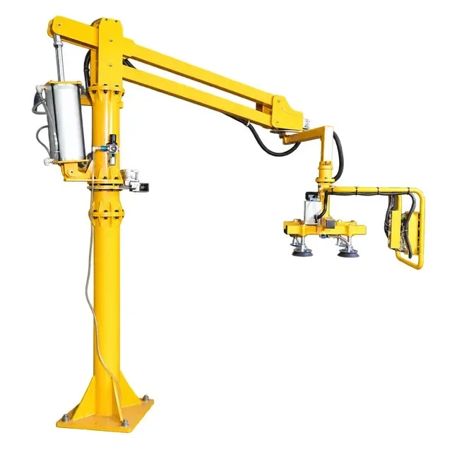
The pneumatic rigid-arm and wire-rope operating instructions describe three protections: an air-cut-off device against sudden arm descent, a safety-valve function that locks the system below its set supply pressure, and joint brakes that restrict free rotation when the arm is parked. The separate soft-rope equipment catalogue describes a slow-descent response to an interrupted air supply or burst line. A locked response and a descending response must not be treated as equivalent, or assigned to a machine from its appearance alone.
Ask which response belongs to the delivered lifting unit and which protection belongs to the end tool. A lifting mechanism that holds position does not establish that a suction head retains vacuum. A joint brake that prevents horizontal drift does not establish that the vertical axis is held. A compressed-air reservoir that supplies a pneumatic circuit is also different from an evacuated reservoir connected to suction pads.
At handover, identify the protected circuit, the trigger condition, the expected arm movement, the gripper response and the approved recovery sequence. Keep the fitted fixture and its drawing with that record. If the machine refuses to lower after a supply problem, do not bypass the safety valve or release a brake to force movement; use the pneumatic manipulator troubleshooting guide to prepare the service observations.
Battery operation does not make all power failures equivalent
A battery-powered lifter does not necessarily lose its working supply when the building mains fails. Conversely, a disconnected battery, an exhausted battery or a fault in a circuit on the machine can stop functions even when the building still has power. Specify which supply has failed instead of describing all four situations as “power off.”
Check the warning system separately: what detects low vacuum, what detects supply loss, and what powers the warning in the relevant failure condition? A warning that works during normal operation does not by itself demonstrate the response to loss of its own supply.
On wheeled glass robots, distinguish vacuum gripping from hydraulic positioning and travel/braking. The fact that one pump still runs does not prove that another function can safely recover the load. The glass robot drive and hydraulic fault guide explains how to identify the affected function without bridging controls or guessing settings.
Why there is no universal holding time
“It has a tank” is not enough to answer “How long will it hold?” Retention depends on the connected evacuated volume, starting vacuum, leakage path, workpiece permeability, pad contact and the minimum vacuum required for the actual load and orientation. Valve state and the failed part of the circuit also matter. A tank size, unloaded gauge reading or pump power cannot establish that duration on its own.
There are also different intervals that should not share one label. Time from source failure to an alarm, time from the alarm to a specified minimum vacuum, and time taken for a tube lifter to descend describe different events. A measured interval ends at its stated acceptance limit, not when a workpiece finally detaches.
A useful retention-test record names the exact machine and fixture, workpiece and lifting face, pad/circuit arrangement, orientation, starting indication, simulated fault, monitoring points, acceptance limit and result. It also identifies the test procedure and person responsible. A value without these conditions is not a reliable basis for another lift.
Have a competent technician arrange any verification under the manufacturer's procedure, with the specified support, restraint and exclusion measures. Do not switch off a suspended production load, disconnect a hose or wait for an alarm to see how much time is available. A failed test must not expose a person to the falling load.
Plan the response before a load is suspended
Before work starts, the trained operator needs to know which warning calls for stopping, how the machine is meant to behave after supply loss, whether controlled lowering remains available, and where the load can be placed. The plan must cover the complete arrangement: a vacuum attachment can retain grip while its separate hoist has lost power.
If a failure occurs, stop the normal handling cycle, keep people clear and use the machine's prescribed emergency response to reach a supported condition where this can be done safely. Do not deliberately release vacuum or disable protection to clear an indication. Do not continue the next lift merely because the pump restarts or mains power returns.
Once the workpiece is independently supported, take the affected equipment out of use and record the symptom before maintenance. Isolation and release of stored vacuum or compressed air belong to the specified maintenance procedure. Record repairs and the required functional verification before return to service.
Questions to settle at purchase and handover
Load and material
Actual workpiece, surface, orientation, permitted load, pad positions and any approved pad isolation.Supply-loss response
What happens to grip, vertical motion and rotation when the relevant electrical or air supply fails?Retention circuit
Which reservoir and non-return valves serve which pads? What remains connected after the specified fault?Warnings
Which conditions are detected, where they are measured, and how the warning operates during the relevant supply failure.Recovery
Required control position, available lowering or recovery method, receiving support and operator training.Verification
Applicable procedure, recorded acceptance limits and results for the identified machine, tooling and workpiece.Changes and maintenance
What needs reassessment after a different workpiece, pad arrangement, hose, valve, source or end tool is introduced?
The inspection checklist helps organize routine checks. For an existing fault, use the fault-report checklist and send the machine identity, fitted tool, observed indications and current supported state to technical support. These details are more useful than a request for a generic “safe holding time.”
Common questions
Does a vacuum reservoir make the lifter safe indefinitely?
No. It provides a finite reserve in the circuit to which it is connected. Leakage still changes vacuum, and the required minimum depends on the approved load and configuration. Use the machine-specific verification and emergency procedure.
If the alarm stops when the pump restarts, can work continue?
A quiet alarm does not explain the cause of the event. After an unexpected supply failure, loss of grip or abnormal movement, follow the equipment's stop, recovery and inspection requirements before resuming. For repeated starts during normal operation, use the pump-cycling and alarm guide.
Does every pneumatic manipulator stay still after an air cut?
No single response applies to all arrangements. Some instructions specify a locking function; others describe slow descent. Confirm the delivered lifting unit and end-tool response together. Do not infer suction retention from the arm's position.
Can I compare two lifters by the number of pads or gauges?
Those visible counts do not establish circuit independence, allowable load after a fault or retention duration. Compare the actual circuit, protected functions and documented conditions instead.
Further reading
The UK Health and Safety Executive's vacuum lifting equipment guidance distinguishes vacuum lifting tubes from vacuum attachments and discusses inspection and emergency planning. It is general UK guidance, not a retention-time specification or approval for an Easytech machine. Use the instructions supplied for the equipment and the requirements applicable at the place of use.