
Start with the failed function, not the regulator
A pneumatic handling manipulator that will not lift does not necessarily need more air pressure. Loss of supply, a restricted line, an unsuitable load or tooling combination, and a lifting-control fault can produce similar symptoms. A machine that will not lower needs a different investigation: on some documented arrangements, a supply interruption activates a protective holding function. Forcing the movement can defeat the very function that is preventing an uncontrolled descent.
This guide covers pneumatic lift-assist manipulators: rigid-arm and cable-supported arrangements with application-specific tooling. It does not cover an electric balancer simply because the equipment looks similar. Identify the delivered machine, lifting mechanism and gripper before comparing a symptom with a fault table.
If the load drifts, the gripper is unreliable or movement is unexpected, stop the task and use the delivered procedure to secure the equipment and load. Do not disconnect a hose, release a brake or change a regulator to see what happens. The observations below concern an event that has already occurred and checks that can be made safely; they are not instructions to reproduce a failure under load.
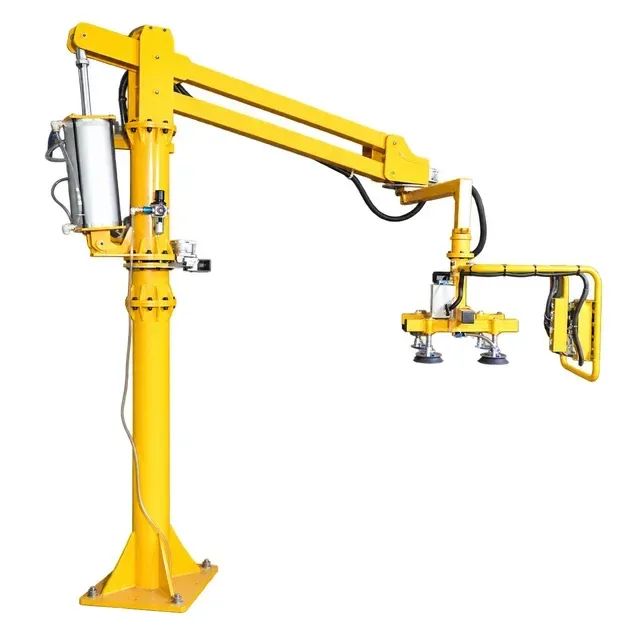
Separate four systems in the service record
1. Supply and air preparation
Record where the machine receives compressed air, the identification of its preparation/regulator assembly, and the location and unit of any existing pressure indication. A factory header reading is not automatically the pressure at the manipulator. A reading taken while idle is not evidence that adequate supply remained available during the reported movement.
2. The lifting mechanism
On a rigid-arm machine, identify the cylinder and linked arms. On a cable-supported machine, identify the lifting unit and suspension. Note which command was given and whether the lifting motion, lowering motion or position-holding function failed. Do not transfer a cylinder-control adjustment to a cable unit.
3. The workpiece tool
A lifting arm can move while a suction tool, clamp or other fixture fails to operate. Record the installed tool and its controls separately. For a suction tool, poor contact is a different observation from a button that does not respond. For a clamp, an observed closure is not proof of the prescribed holding condition.
4. Rotation, brakes and travel limits
Describe the joint or axis involved and whether a brake was intended to be applied. A hose reaching its travel limit, an obstruction and a fault at a joint can all feel like “the arm is stiff.” Pulling harder does not distinguish them.
Match the symptom to the next useful evidence
The manipulator will not lift
Record: whether this began at startup, after a supply interruption, after a tool change or with a different workpiece. Include the last successful task, the actual workpiece identity and weight if known, and the installed tooling.
Service review: the documented fault tables direct attention to unavailable or insufficient air supply, kinked or disconnected lines and operation outside the applicable load condition. Confirm the machine-and-tool rating rather than assuming the largest number on a family page applies. Added tooling and changed workpiece geometry require configuration review.
Do not infer: that increasing pressure will restore an approved load rating, or that a moving unloaded arm proves the loaded task is suitable.
The manipulator will not lower
Record: whether the load stopped after a pressure loss, which controls remained responsive and which indications or alarms were visible. Preserve the event sequence: command, movement, interruption, final state.
Service review: certain documented pneumatic arrangements hold after a supply interruption through their protective circuit. The technician must identify that circuit and its recovery procedure. Other causes remain possible; “will not lower” alone does not prove that protection operated.
Do not infer: that every manipulator will safely hold any load after loss of air. Do not vent a line or bypass an interlock to release a suspended workpiece.
Both lifting and lowering are slow
Record: whether the change affects the whole travel or one position, both directions or one, all workpieces or one format, and whether other pneumatic functions changed at the same time.
Service review: the fault tables include supply limitations, restricted/kinked lines and cylinder flow-control conditions. A technician can use the installed circuit and approved test method to separate these. A restriction near a moving joint deserves particular attention when the symptom changes with arm position.
Do not infer: that there is a universal valve-opening direction or number of turns. An adjustment may change motion and the handling behaviour of the complete system.
The arm or load slowly descends without a command
Record: the location of the movement, whether the tool also moved relative to the workpiece, the arm position and any previously observed air-leak sound. Keep the machine out of service pending the prescribed assessment.
Service review: the manual lists local pipe or joint leakage as a possible cause of slow automatic lowering. That is a starting point, not a diagnosis of every drift event. Tool grip, lifting position and workpiece movement must be distinguished.
Do not infer: that a small or slow movement is acceptable. The available documentation does not establish a universal allowable drift rate.
A fixture button does not work
Record: the button identity, the intended action and whether other buttons still operated. Note a recent fixture exchange, hose reconnection or change in supply.
Service review: supply, the relevant control circuit, line condition and the actual valve/fixture arrangement. If the arm still moves, that narrows the observation but does not prove that the tool is receiving the required supply or command.
Rotation is obstructed or rough
Record: the exact joint and approximate working position where the problem was first observed. A safe overview photo and a separate photo of the hose routing are more useful than “rotation problem.”
Service review: kinked lines, the intended travel limit, brake state and physical interference. The manual mentions limits and hose routing; it does not authorize an operator to reposition a stop to gain more reach.
Why one pressure number cannot diagnose the machine
Write down a pressure value only with its unit, measurement location, operating state and the applicable machine instruction. Different documents and configurations may specify different supply or inspection conditions. Combining those values into one “correct pressure for pneumatic manipulators” loses the information needed to interpret the reading.
For example, an unchanged idle gauge reading and slow movement can coexist. The useful question is whether the approved measurement shows the required supply at the relevant location and operating condition. That assessment belongs to the qualified service process, not a trial-and-error regulator change by the operator.
Use the history to narrow the investigation
When the problem began | Information to compare |
|---|---|
First commissioning or relocation | Delivered configuration, site supply, installation handover and any unresolved commissioning checks. |
Immediately after maintenance | Exactly what was disconnected, replaced or adjusted; fitted part identification and the service record. |
After a new fixture or workpiece | Approved tool/load combination, workpiece geometry, grip method and any changed control function. |
Only near a particular arm position | Joint identity, hose path, working limit and nearby obstruction. |
After a shared air-supply interruption | Time of interruption, affected functions, final load state and the installed recovery procedure. |
These are investigation branches, not reported failure statistics. A change that occurred just before the fault is relevant evidence, but is not by itself proof of the cause.
Prepare a service handover that can lead to a repair
Download the pneumatic manipulator service record. Record the machine and tool identity, failed function, event sequence, existing indications, recent changes and present safe status. Attach a whole-machine photo, identification labels, the relevant joint or tool, and hose routing where it can be photographed safely. Do not create a new loaded demonstration for the report.
Service closure should identify the cause, the approved correction and the prescribed checks of motion, grip/release and protective functions before return to use. Merely making the arm move again does not close a tool-grip or position-holding fault. Keep the completed record with the equipment instructions.
Questions about pneumatic manipulator faults
Is a manipulator the same as a pneumatic hoist?
Not necessarily. “Lift assist,” “handling manipulator,” “balancer” and “hoist” are sometimes used loosely. The lifting mechanism, controls and workpiece tool determine which instructions apply. See the comparison of manipulators, balancers and hoists before using a fault procedure for a different device.
If the arm works, can the gripper be ruled out?
No. The lifting and tool functions need separate observations. An arm that moves does not establish a secure suction contact, correct clamp operation or successful interlock sequence.
Should a machine that will not lower be depressurized?
Not as an improvised recovery action under load. Identify the installed holding and recovery arrangement and follow its instructions. Planned maintenance also requires control of stored energy and protection against unintended movement.
Technical basis and related guidance
This guide synthesizes Easytech pneumatic rigid-arm and cable-manipulator fault and maintenance documentation. The repeated fault entries in related manuals are treated as shared guidance, not independent test results. The photograph is a configuration example, not a diagnosed failure. No universal pressure setting, drift allowance or loss-of-supply holding time is asserted.