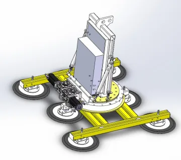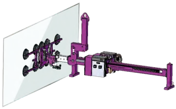
For a large glazed unit, the lifting plan starts with the entire pane and its route into the opening. A lifter must support the permitted contact areas while the crane, rigging and frame fit the actual working position. The heaviest-rated frame is not automatically the easiest to place or withdraw.
Choose the frame around the pane and the movement
Model / configuration | Rated load | Standard pad dimensions | Standard number of pads | Tilting | Rotation |
|---|---|---|---|---|---|
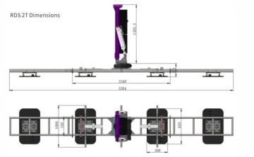
2000 kg | 850 × 550 mm | 4 pcs | 0–90° | 360° continuous | |
3000 kg | 850 × 550 mm | 8 pcs | 0–90° | 360° continuous | |
5000 kg | 850 × 550 mm | 10 pcs | 0–90° | 360° continuous | |
10000 kg | 850 × 550 mm | 20 pcs | 0–90° | 360° continuous |
These RDS configurations use rectangular pads for their standard arrangement. Their optional curved-glass pad groups require a separate load confirmation. Do not carry a standard flat-glass rating across to the curved option.
When manual movement, powered movement or offset reach matters
Handling constraint | Configuration to examine | Decision |
|---|---|---|
2,000 kg; 20 × Ø300 mm pads; manual 90° tilt and 360° rotation; equipment 2,600 × 1,300 × 400 mm; stated maximum pane 3,600 × 8,000 mm. | Check manual positioning access and frame clearance as well as the pane dimensions. | |
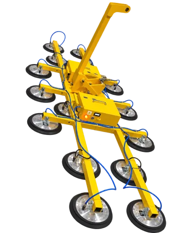
ET-GL-HYD-1500-LEG — Dual-Circuit Hydraulic Glass Vacuum Lifter | 1,500 kg; eight Ø400 mm pads; two vacuum circuits; hydraulic tilt and rotation. Optional wireless control operates tilt, rotation, gripping and release. | Review the extended frame arrangement and crane load, including the lifter mass and rigging. |
Counterbalanced configuration; 2,000 kg headline maximum; 1,200 mm arm extension stroke. | Use the configuration load chart for an offset installation. Extension stroke is not a universal 2,000 kg reach. |
Work backwards from the glazing pocket
Mark the final pane position, building projection and crane-hook line on a section drawing. Add the space occupied by the pads, frame, suspension and any offset arrangement. Then trace the approach, alignment, temporary support and release. A frame that can lift the pane at ground level may still obstruct the final opening.
For glass with holes, frit, coatings or narrow edges, show the allowed contact zones. Include the pane construction and the glass supplier’s lifting instructions. The pad layout must also address pane flex; additional nominal pad area cannot compensate for unsuitable support spacing.
What a useful installation review should deliver
- An identified pane range and allowed pad positions, with the quoted frame layout.
- The complete suspended mass for crane and rigging review, distinct from the pane weight.
- The required tilt, rotation and reach at each constrained step.
- A documented release position after the pane is independently supported, with space to remove the frame.
Does a 5-tonne model mean the glass in its photograph weighs 5 tonnes?
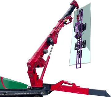
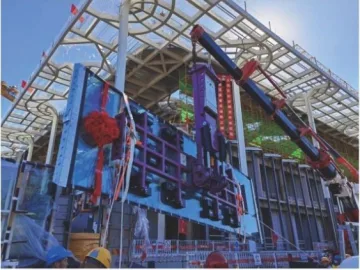
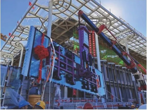
No. RDS-5T identifies an equipment rating. An application photograph shows an arrangement, not a measured pane weight or approval for another installation.
Can I remove pads to fit a narrow pane?
Only within a documented configuration with the applicable revised rating. Disconnecting pads changes the support pattern and vacuum arrangement; do not retain the full-frame rating by assumption.
Details to include in your enquiry
Requirement | Details to provide |
|---|---|
Pane | Complete dimensions, weight, thickness, centre of gravity, cutouts and surface/coating details. |
Contact plan | Usable face and proposed pad positions across the pane. |
Lifting system | Supporting crane/hoist, attachment weight and required working position. |
Movement | Start/end orientation, tilt/rotation and site clearances. |
Choose the next step
Glass vacuum lifter selection · Heavy-glass application record · Glass lifter configurations