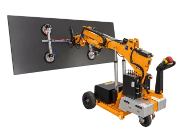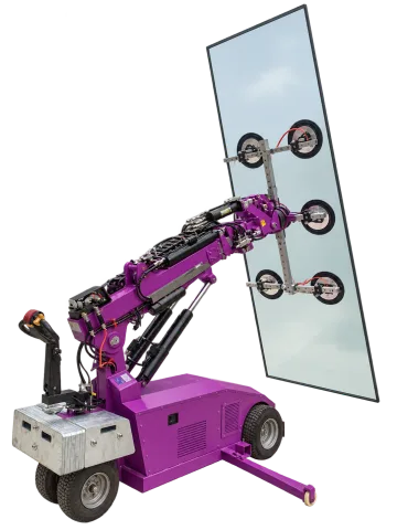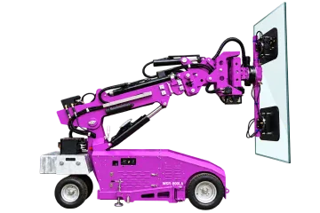
Choose glass installation equipment by the entire route from rack to opening. A mobile robot needs suitable access and a matching working envelope; a suspended lifter needs an appropriate crane or hoist and room for its rigging. Both need a pad arrangement that suits the pane.
Compare the route before choosing the format
Project constraint | Route to consider | Critical input |
|---|---|---|
Restricted indoor route | Compact wheeled robot. | Door and turn geometry, floor capacity, working height and reach. |
Larger pane with powered fine positioning | Robot with the documented positioning functions. | Pane weight at the required outreach, access route and load chart. |
Crane already covers the installation point | Suspended glass vacuum frame. | Complete suspended load, hook position, rigging and withdrawal clearance. |
Curved or offset glazing | Dedicated curved or counterbalanced arrangement. | Curvature/contact face or setback drawing and applicable configuration rating. |
Robot dimensions can change the access decision
Model / configuration | Maximum rated load | Maximum lifting height | Minimum overall dimensions | Equipment weight |
|---|---|---|---|---|
400 kg | 3200 mm | 1298 × 730 × 1852 mm | 815 kg | |
800 kg | 4600 mm | 3100 × 880 × 1620 mm | 1925 kg | |
800 kg | 4600 mm | 3235 × 880 × 1620 mm | 2190 kg |
WSR-400MINI lists a 730 mm minimum equipment width; WSR-800L and WSR-800LA list 880 mm. These are machine dimensions, not minimum doorway approvals: add the carried pane, turning sweep, attachments and required clearance. Their maximum lifting heights are not full-load heights.
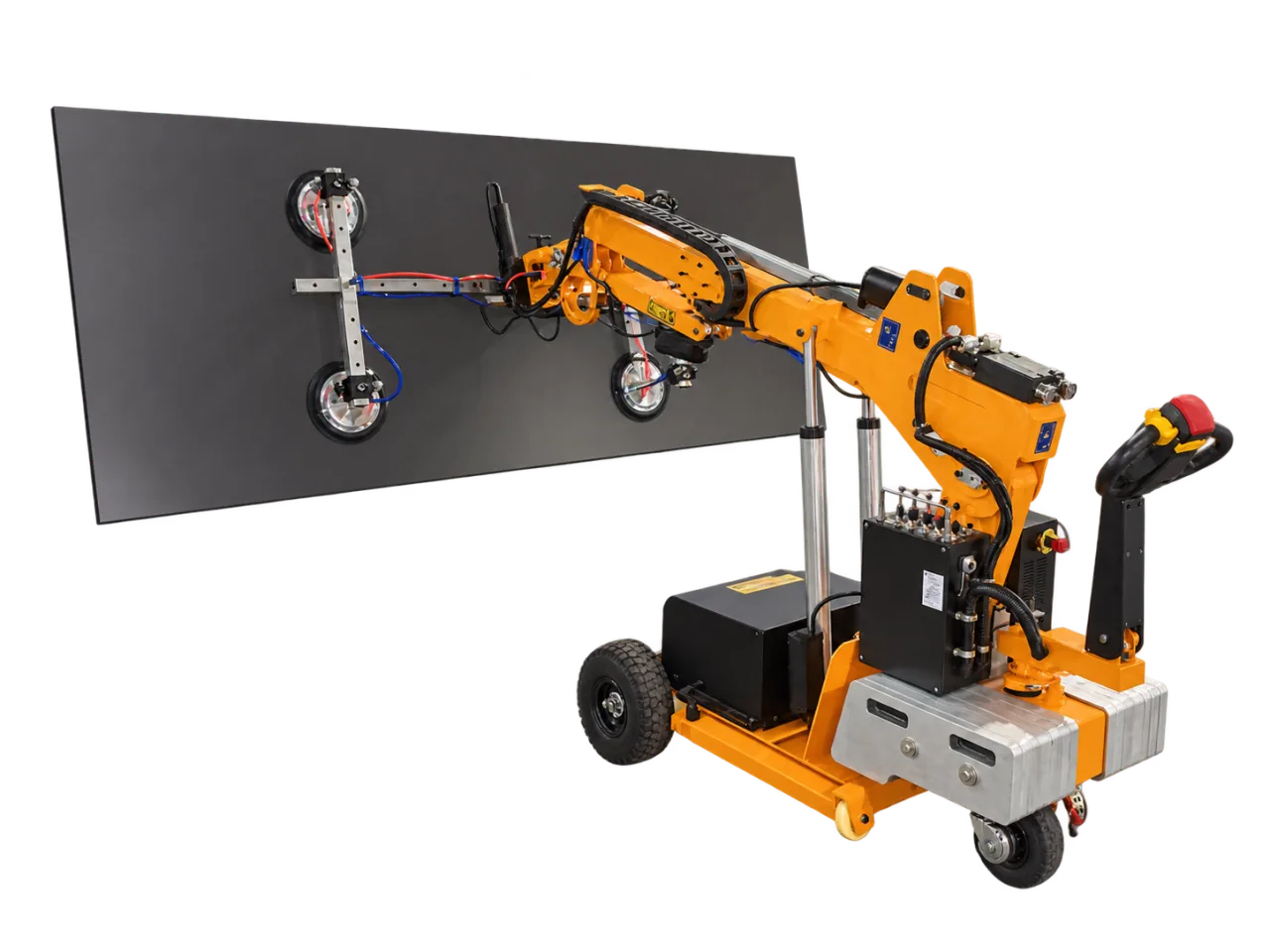
The two 800 kg robots have different contact and movement details
WSR-800L has six Ø400 mm pads and side turning of left 90° / right 15°. WSR-800LA has two 500 × 800 mm pads, 90° side turning each way and ±75 mm vertical fine adjustment. Select from pane contact and alignment needs; the shared 800 kg headline does not make them interchangeable.
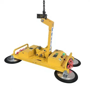
ETJSB-G400B — H-Frame Glass Vacuum Lifter — 400 kg H-frame suspended lifter with four Ø300 mm pads and manual tilt/rotation. A suitable supporting lifting machine remains part of the installation system.
Check every constrained stage
Stage | Record |
|---|---|
Unloading / rack pickup | Rack orientation, pane contact face and access for the frame. |
Travel | Narrowest opening, turning area, gradients, ground/floor and overhead limits. |
Installation | Height and horizontal setback at the actual pane position. |
Alignment | Required tilt, rotation, side turn and fine adjustment; distinguish powered from manual movement. |
Release | How the pane is secured independently and how the equipment withdraws. |
Can maximum height and maximum capacity be combined?
No. Check the configuration-specific load chart at the required position. A robot’s headline maximum values describe separate limits.
Does an outdoor photograph prove suitability for my site?
No. It records a particular arrangement. Ground bearing, wind, slope, access and operating restrictions must be established for the selected equipment and project.
Details to include in your enquiry
Requirement | Details to provide |
|---|---|
Glass | Dimensions, weight, centre of gravity, curvature/coatings and usable pad areas. |
Access | Unloading point, doors, turns, floor/ground and overhead restrictions. |
Installation | Required height, reach, orientation and alignment clearance. |
Equipment | Robot working envelope or crane/hoist arrangement, lifter weight and pad configuration. |
Choose the next step
Robot or suspended lifter · Read the robot load chart · Glass vacuum selection
Build the complete handling sequence
Connect rack access, machine transport, installation reach and final pane support in one requirement sheet.