
What causes a vacuum lifter to lose suction?
Vacuum lifter suction loss can result from damaged seals, leaking connections, restricted hoses or filters, unsuitable workpiece contact, supply problems, or changes during movement. A running pump does not rule these out. Start by separating failure to establish vacuum, slow evacuation, abnormal behaviour while stationary, problems during movement, and a mismatch between the indication and the actual grip. Replacing the pump before making that distinction may miss the cause.
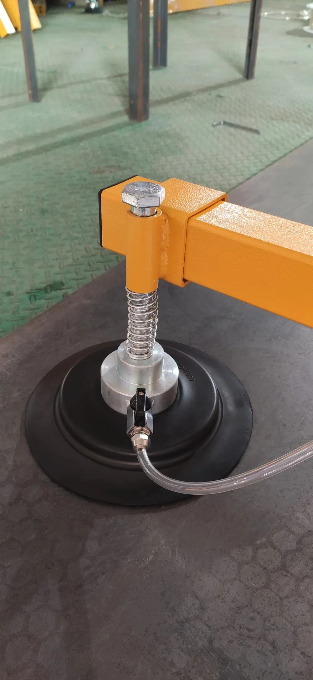
Follow the physical fault path
The real assembly shows a rubber sealing edge against sheet metal, a transparent hose, its connection and a local valve. Above it, a spring-mounted support joins the pad to the frame.
Start with the actual contact and air path. A worn sealing edge, a leaking fitting and a restricted hose can produce different faults even when the pump runs.
The photographs identify components, not confirmed defects or valve operating positions.
This article concerns suspended vacuum pad frames used with lifting equipment to handle sheet materials. Vacuum tube lifters, self-propelled glazing robots and specialised multi-circuit systems have different operating and protection arrangements; the discussion is not a service procedure for those machines.
Make the equipment and load safe first. Stop using equipment with abnormal grip, slip or warnings and follow its prescribed safe-response procedure. Do not recreate a hazardous lift for diagnosis. Maintenance requires an unloaded machine, the specified energy isolation and competent personnel; energised diagnostics require an approved service procedure. Do not bypass alarms, remove filtration to continue lifting, or switch off a loaded system to estimate suspension time. [1][2]
Keep the operating and maintenance guidance with the diagnosis.
Read the English guide for pre-use checks, handling checkpoints, component care and a service-record checklist.
Read the guide · Download PDF (6 pages)
1. Start with when the problem happens
Failure to attach before pickup and loss of grip during transport call for different investigations. Easytech’s operating and maintenance material treats these as separate fault groups, summarised in the linked English guide. Before pickup, possible causes include leaking connections, blocked filters or silencers, damaged seals, valve state and workpiece porosity. The transport group also identifies kinked hoses, lifting acceleration, multiple pieces being picked up and electrical connections. [1] The distinction matters: the stage of failure helps determine what to investigate.
Table 1. Use symptoms to narrow the investigation, not to condemn a component.Observation | What to investigate | What it does not establish |
|---|---|---|
The source runs but the required vacuum condition is not reached after contact. | Full pad contact, seals, hoses, joints, actual valve state, the workpiece surface and porosity, and the source supply. | Motor noise neither proves the pump is performing correctly nor proves it has failed. |
The former reading is eventually reached, but the wait is longer. | Restricted filtration or pipework, kinks, supply changes, and changes to connected volume or pad configuration. | Longer evacuation is not unique to leakage. The same final reading does not mean the same cycle performance. |
The indication changes abnormally after attachment while stationary. | Sealing, connections, the surface, valve and circuit state, and the control mode. Record whether the source is running. | A pressure change while the source is supplying vacuum is not an isolated pressure-rise measurement. |
No stationary symptom is seen, but a warning appears during lifting or travel. | Workpiece flexure and support, pad loading, centre of gravity, moving hoses and connections, and unintended multiple-sheet pickup. | Stationary attachment does not qualify the moving task. Slower operation does not automatically close the fault. |
The indication appears normal, but the load slips or some pads are not participating. | Measurement location, isolated branches, effective contact, load direction, surface friction and approved configuration. | A manifold reading does not demonstrate attachment at every pad or adequate resistance to sliding. |
A problem limited to a new coated, damp or otherwise changed batch makes the workpiece change worth investigating. A problem affecting several previously satisfactory workpieces points attention toward shared equipment or supply changes. These are priorities for investigation, not mutually exclusive diagnoses: a surface change and an equipment defect can coexist.
2. Define what “the pressure drops” means
Vacuum descriptions can reverse the meaning of a number. On a gauge referenced to local atmospheric pressure, a change from −60 kPa to −40 kPa means weaker vacuum, even though the signed number has increased. An absolute-pressure instrument also moves towards a higher number as vacuum weakens. A display expressed as vacuum percentage or unsigned vacuum magnitude behaves differently. Record the actual reading, unit and instrument type. These example readings are not lifting thresholds.
−60 kPa → −40 kPa = weaker vacuum
Gauge-pressure terminology example only. These are not permitted lifting thresholds.
Also identify the measurement location. Consider a severe restriction between the vacuum source and the pads. A source-side measurement may reach a lower pressure before the pad side has been adequately evacuated. That is an explanation of why location matters, not a claim that every lifter has this circuit arrangement.
Why can both a leak and a restriction slow attachment?
A leak adds air to the system; a restriction limits its removal. Either can lengthen evacuation, but the remedies differ. A damaged seal, a connection or the workpiece can admit air. Filtration, a hose or a valve can restrict the flow path. Easytech’s troubleshooting documentation identifies both groups, so investigating the flow path and sealing is part of diagnosis—not an optional step after replacing the pump. [1]
A useful comparison records the time from contact to the manufacturer's required condition on the same machine with a comparable surface, supply and effective configuration. The starting condition and measurement point also need to match. A longer hose or a change in connected internal volume can change that time even without the same fault. A single statement such as “it takes several seconds” leaves too much undefined.
Does continuous running or repeated starting mean the pump is faulty?
First establish whether the machine is designed for continuous operation or pressure-controlled cycling. Continuous operation alone is not a fault in a continuously operated system. In a cycling system, a marked departure from its documented baseline deserves investigation, alongside surface condition, seals, valve state, reservoir volume and supply. Neither a familiar motor sound nor an unexpected pause is enough to diagnose the entire system.
Our separate guide to vacuum source selection explains the different roles of pressure and airflow. For troubleshooting, the immediate questions are where air may be entering, where its removal may be restricted, and which part of the circuit the instrument is describing.
3. A normal reading does not verify the pad configuration
The operating documentation underlying the English guide requires the specified pads to be installed and connected for the documented maximum-load configuration. Removing or disconnecting pads changes that condition. A pad physically fitted to the frame is not necessarily contributing to the load. [1] These are configuration constraints in a particular document, not permission to scale the capacity of any lifter by pad count.
Pads installed, pads connected to vacuum and pads making effective contact are not necessarily the same set. If a branch is isolated, the remaining manifold may still show a strong vacuum. That reading does not restore the missing pad contribution. Rearrangement also changes support, overhang and loading. This article therefore offers no shortcut for calculating how much can be lifted with fewer pads.
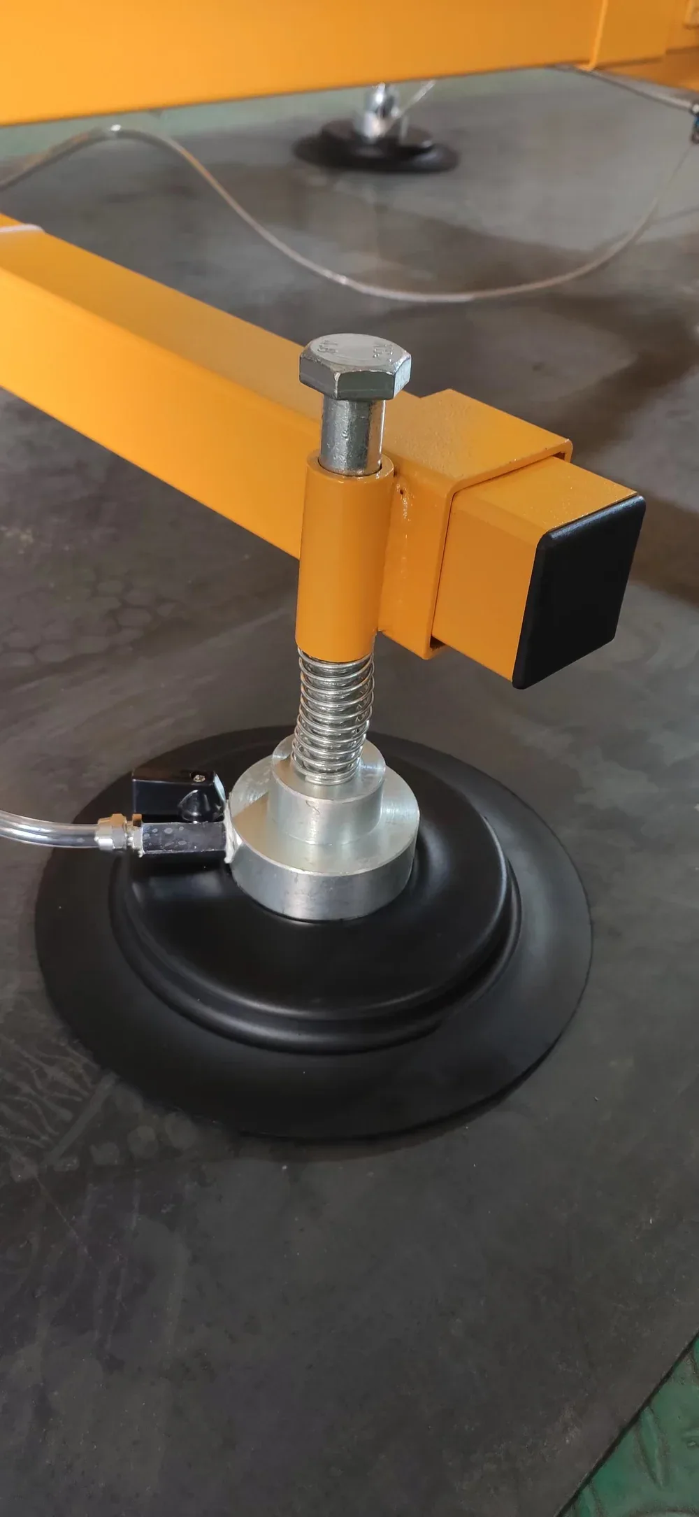
Check support as well as suction
This second view shows the pad mount, support spring, fastener and hose connection. The hose continues between assemblies across the workpiece.
The pad is mechanically attached to the frame through the support assembly. Inspect condition and routing using the applicable manual; a spring or fastening that looks intact in a photo is not evidence of a verified load rating.
The photographs identify components, not confirmed defects or valve operating positions.
The operating documentation also addresses hose pinching or kinking during movement, workpiece overhang and the effect of moisture on slip resistance. [1] Investigation must extend beyond the vacuum circuit: an unsuitable support arrangement or loose mechanical connection is not corrected merely because a gauge reading recovers.
Schmalz distinguishes theoretical suction force from other loading conditions, including shear, and explains the importance of application conditions. [3] The practical consequence is straightforward: a vacuum reading is one condition to evaluate, not certification of the complete handling arrangement.
When the problem appears only during motion
“It alarms when moving” can be made more useful. Existing observations may identify initial separation from the support, acceleration, a change of direction, a position where a hose bends, or another repeatable part of the route. Do not repeat a hazardous event to obtain that detail.
The maintenance material lists excessive lifting acceleration and unintended pickup of several pieces separately. One changes the dynamic demand; the other changes the actual load being handled. Neither is automatically resolved by a stronger vacuum reading. Use the approved motion limits for the actual machine and configuration. Reducing travel speed is not a substitute for correcting damaged connections or unsuitable contact.
4. Longer vacuum retention does not necessarily mean less leakage
For an isolated, known volume at approximately constant temperature, the average gas load associated with a pressure rise is q ≈ V × Δp / Δt. Outgassing can contribute, so the result is not automatically a pure leak rate. [4] This helps interpret a technician's approved test report; it is not an instruction to isolate the vacuum source of a loaded lifter.
HYPOTHETICAL EXAMPLE · NOT EQUIPMENT TEST DATA
Identical pressure rises, different calculated gas loads
Quantity | Test volume A | Test volume B |
|---|---|---|
Effective volume | 2 L | 10 L |
Absolute-pressure rise in 20 s | 4 kPa | 4 kPa |
Average calculated gas load | 0.4 kPa·L/s | 2.0 kPa·L/s |
Assume stable volume and temperature, an isolated source and comparable measurements. B has five times the calculated gas load, despite the identical pressure-change rate. Comparing only elapsed time and pressure change would hide that difference.
These figures are not allowable leakage, a pump-selection flow rate, a load rating or a safe suspension time. Adding storage volume is not a remedy for a defective seal. Acceptance conditions belong to the actual machine and approved configuration.
When a report says retention is satisfactory, ask which circuit was measured, whether its effective volume was comparable, whether the source was replenishing vacuum, what contact surface was used, and how conditions were recorded. A retention time without its conditions is insufficient to compare machines or establish their behaviour following a power failure.
5. Turn observations into a repair or application decision
A useful investigation separates what was observed from what remains unknown. The following illustrative scenarios show how to reason from the evidence. They are examples, not reports of customer incidents.
SCENARIO A
Evacuation becomes slower after a filter change
Check the part identity, installation, connections and service record before attributing the change to pump wear. If the approved correction restores the former timing, that supports an involvement of flow restriction. It does not, by itself, verify every other part of the machine.
SCENARIO B
A reference surface works; a new batch does not
Investigate surface condition, film, flexure and contact. Success on an easier surface does not prove the equipment is fault-free: a degraded system may still handle that condition. A competent person should conduct any comparison under an approved procedure and document configuration and supply.
SCENARIO C
A warning occurs during travel, then clears
Recovery while stationary does not establish that a fault has repaired itself. Use the existing event record to investigate hoses, connections, layout, the workpiece and relevant controls. Return to service requires the machine's prescribed verification after the identified issue has been addressed.
What closes the investigation?
A defensible record connects the original symptom and conditions to the defect or unsuitable application found, the actual corrective action, the relevant verification under approved conditions, and the required return-to-service decision. “Pump replaced”, “cleaned” and “no alarm for now” leave gaps in that chain.
Damage, obstruction or an incorrect part calls for the appropriate repair. A move to a different surface, size or motion may require a new application assessment even when the machine still works correctly on its original task. Maintenance restores the intended condition; application selection establishes suitability for a changed task.
Table 2. Information that makes a technical record useful.Record | Useful detail |
|---|---|
Machine and configuration | Model, serial number, manual revision, installed/connected/contacting pad states, and recent configuration changes. |
Workpiece | Material, dimensions, thickness, verified weight, surface or film, affected batch, and whether one piece was being handled. |
Pressure and time | Actual readings and units, instrument type and known location, operating stage, source state, and existing records using the same time reference. |
Motion and supply | The recorded stage or position, relevant electrical or compressed-air supply information, and visible hose or connection condition. |
Action and outcome | What was found, what changed, the verification procedure and responsible person; retain any unexplained symptom explicitly. |
Use our vacuum lifter fault-reporting page when preparing a support request. Include the equipment identification, a clear photo of the overall configuration, the affected component and any existing instrument records. Do not repeat a hazardous lift to obtain evidence.
6. Specify the evidence before buying the equipment
Fault analysis also improves purchasing. Agreeing how suitability and normal behaviour will be assessed before delivery avoids arguments based on different assumptions. Beyond maximum load and pump power, ask the supplier to define:
- The workpiece and configuration: applicable surfaces, dimensions and motions; permitted pad adjustments; and the supporting configuration-specific capacity information.
- The conditions for lifting: which indication to use, what it represents, and the response to a warning. Do not transfer an unverified threshold between models.
- Reference behaviour: how attachment is recorded under the agreed workpiece and supply conditions, and which changes require investigation. An unconditional promise of attachment “in seconds” omits essential information.
- Delivery and service information: the applicable operating instructions, circuit information, component identification, maintenance requirements and return-to-service procedure.
The aim is to identify whether the next action is maintenance, repair or a renewed application assessment. Linking the failure stage to the measurement point, supply, workpiece and effective configuration is more informative than repeatedly replacing the most visible component: the vacuum pump.
Frequently asked questions
Will a bigger pump stop a vacuum lifter losing suction?
Not necessarily. A larger source does not repair damaged seals, restore missing pad contact or correct an unsuitable configuration. Establish whether the problem is leakage, restricted flow, supply or application suitability before changing the source. Any change must remain within the manufacturer’s approved configuration.
Can a vacuum lifter slip while the gauge looks normal?
Yes. The gauge describes pressure at its measurement point. It does not independently verify every pad’s contact, surface friction, support arrangement or loading direction. Treat observed slip as a fault requiring safe shutdown and investigation, even if the indication appears familiar.
Is there one vacuum reading that is safe for every lifter?
No. The permitted operating condition depends on the machine, configuration and application. Use the specified indicator and criteria supplied for that equipment. The example readings in this guide explain terminology only.
EQUIPMENT SUPPORT
Send the observations that help identify the cause
Share the model and serial number, pad configuration, workpiece details, exact indication and the stage at which the issue appeared. Existing photos and records are enough to start the conversation.
Prepare a fault report · Identify a replacement part
Technical references
This guide combines equipment documentation with vacuum engineering principles. The calculation and scenarios are illustrative; the instructions supplied with the individual machine govern its operation and maintenance.
- Easytech: Vacuum Lifter Operation & Maintenance Guide, ET-OM-PAD-EN-01, 14 October 2026. See pre-use checks, component care and troubleshooting. Read the English PDF. This supplementary guide does not replace the valid instructions supplied for the individual machine.
- HSE: Vacuum lifting equipment. Guidance on safe use and maintenance of vacuum lifting equipment.
- Schmalz: Technical data of suction cups. Suction force, shear loading and application conditions.
- Leybold: Definition and measurement of vacuum leaks. Pressure change, gas load and the limits of leak-rate interpretation.