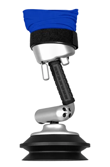
A vacuum tube lifter can make contact with a load yet fail to raise it because gripping, lifting and height control depend on the complete tube–head–source combination. The useful starting point is the symptom: weak contact, insufficient lift, abnormal unloaded hover, loss of grip during lowering, or insufficient travel. Each points to a different set of checks.
Record the installed control head, actual package and stage of movement before changing anything. A familiar model name, a running blower or a vacuum reading on its own cannot identify the cause.
Before investigating: stop using a system with unexpected movement, poor grip or a warning. Follow its prescribed procedure to place the load safely and keep people clear. Inspection or disconnection requires the load to be supported and the relevant energy sources isolated. Energised diagnosis belongs to a competent person following the approved service procedure; do not recreate a hazardous lift for this guide.
1. Identify what actually produces the lift
In a vacuum tube lifter, the source removes air from a flexible lifting tube and the suction tooling. The pressure difference provides grip at the workpiece and produces the lifting action as the tube contracts. The operator uses the control head to regulate movement. A hook-suspended vacuum attachment has a different arrangement: its suction system grips, while a separate hoist or machine performs the lift. The UK Health and Safety Executive makes this distinction in its guidance on vacuum lifting equipment.
For diagnosis, identify five parts of the installed tube-lifting station:
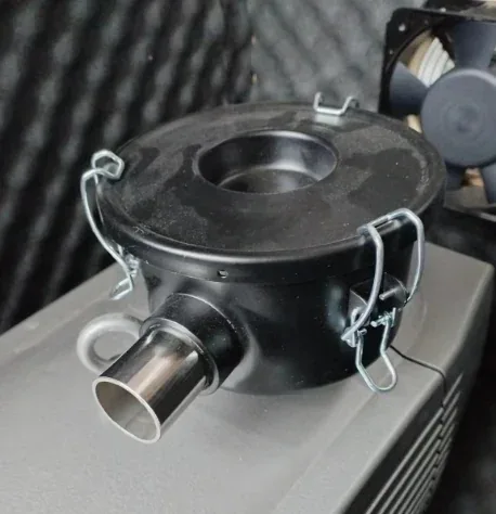
- Vacuum source and filter: the pump or blower, its filtration and the electrical supply specified for that installation.
- Supply hose and upper connection: the path between the source and the lifting unit, including the upper swivel where fitted.
- Lifting tube: the large flexible lifting member that changes length. It is a different component from the supply hose.
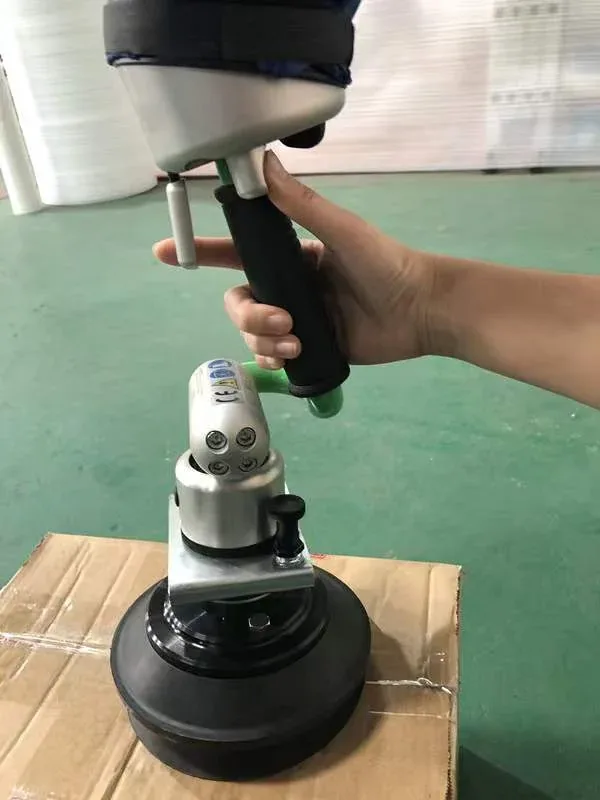
- Control head: the handle, operating valves and the provisions for the specified unloaded hover setting.
- Suction tooling: the pad or head, its connection and its contact with the actual package.
This distinction prevents a common mistake: treating every failure to rise as a bad suction pad, or treating a head that rises unexpectedly as evidence of a stronger, healthier vacuum system. Contact, motion and control response need to be considered together.
2. Start with the symptom, not a replacement part
The following symptom checks organise an event that has already occurred. The possible causes are investigation branches, not diagnoses established by the symptom alone. Record information from a safe position; do not continue lifting to complete the record.
The head does not establish reliable contact
Distinguish: Package/seal mismatch, an open or leaking connection, restricted flow, or a source/supply problem.
Record: Package face and seams; fitted head; recent changes; indicated vacuum and measurement location, if available.
The head appears to grip, but the load does not rise
Distinguish: The applicable load limit, package permeability, the source–tube–head combination and the control condition.
Record: Actual filled weight; sealed/porous load specification; control-head identity; whether this exact package was previously handled successfully.
The empty head keeps rising to its upper position
Distinguish: Unloaded hover/control setting, the installed head assembly and flow-path condition. Easytech’s tube-lifter fault table identifies both hover setting and filtration as checks.
Record: Whether there is no workpiece; any head/filter change; which control is fitted; when the behaviour began.
Grip deteriorates while lowering
Distinguish: Lowering versus release actuation, package deformation, and the contact/airflow condition during the event.
Record: The control being used; the point at which grip changed; whether the head tilted, a seam opened or a hose moved.
Only one package type or batch causes trouble
Distinguish: A change in contact, permeability, stiffness, weight or the approved head combination.
Record: Filled package photographs, batch differences, seam/tape locations and the previously accepted package specification.
The load rises, but cannot reach the required destination
Distinguish: Available lifting stroke, installation height and tool/workpiece clearance, as well as any genuine loss of performance.
Record: Pickup and placement heights, the tube’s position when movement stopped, and the complete station layout.
If the main problem is a vacuum reading that builds slowly or falls away, use the companion vacuum lifter suction-loss diagnosis guide for the distinction between leaks and restrictions. The sections below address what is specific to tube lifting.
3. Check the load condition before treating “no lift” as a fault
A model’s largest published kilogram figure may apply to a sealed contact surface. Bags and cartons can behave differently. Their permeability, seams and deformation affect the contact arrangement; the weight written on the package is only one input.
Examples from Easytech’s current tube-lifter data, cross-checked against the 2026 catalog
Model | Sealed surface | Loose / porous surface |
|---|---|---|
30 kg | 25 kg | |
40 kg | 35 kg | |
50 kg | 45 kg |
These are conditional product values, not a statement that every bag or carton below the listed mass is suitable. The delivered configuration and its approved workpiece/head combination still determine permissible use.
A load mismatch that can resemble a machine fault
Consider an illustrative 40 kg porous package proposed for ETJSQ-V120-40. Its mass matches the 40 kg sealed-surface figure but exceeds the 35 kg porous-surface figure. This is a mismatch to resolve before attempting the task, not a reason to turn up a control or replace the pump. ETJSQ-V140-50 has a higher published porous-surface value, but that alone does not approve the package or make every head compatible.
The handle is part of the configuration
The Type A single-hand control lists a maximum compatible bag load of 45 kg. A higher-rated lifting unit does not remove that application limit. Conversely, the Type C extended two-hand control lists a series maximum compatible load; it does not give every machine fitted with that handle the same capacity.
When a head or handle has been changed, review the complete approved combination, including the connection, tooling mass and the contact pattern. Components that fit physically are not automatically an approved lifting assembly.
4. Separate unloaded hover, lifting and release
Unloaded hover is the position of the control/head assembly without a workpiece. It is not a promise that a loaded machine can be left unattended. Easytech’s tube-lifter operating materials describe unloaded suspension adjustment separately from loaded operation, and reserve one loaded-setting procedure for a particular rocker-lever control.
The distinction matters after a tooling change. A different head changes the suspended assembly as well as the contact with the workpiece. An empty head that no longer stays at its intended position needs its configuration and prescribed setup checked; its behaviour does not prove that the same head will safely handle a load.
“More airflow” can mean two different things
The source removes air from the vacuum circuit. The control unit can admit air to regulate the vacuum and the lifting response. Those are different flows. In the unloaded-control arrangement described in Easytech’s documentation, increasing admitted air lowers the hovering position; restricting that admission raises it. This explains why “increase airflow” is an incomplete instruction unless the relevant path and control have been identified.
It also explains why a restriction at a filter cannot be treated as equivalent to changing a control valve. The filter is in the evacuation path; the control acts on the machine’s operating balance. A service diagnosis needs to establish which part is involved.
Match the control, not just the appearance of a lever
The reviewed range includes single-hand, rocker/joystick and extended two-hand arrangements. Their operating and release controls differ. On a configuration with a separate release control, release must not be mistaken for normal lowering. The load must be fully supported before the prescribed release action.
Confirmed direction for the rocker-lever loaded-hover adjustment
For the rocker-lever control unit’s loaded-hover adjustment screw, identified as Pos. 3 in section 5.3 of manual ET20170850V6, the manufacturer has confirmed that clockwise lowers the loaded hovering position; anticlockwise raises it. This confirms section 5.3 and corrects the opposite direction stated in section 6.2, item 6 of that manual.
This clarification concerns the identified loaded-hover adjustment, not the unloaded-hover screw, the normal operating lever or the release control. It is not a direction rule for every control head. Before adjustment, the responsible technician must identify the matching assembly and screw and establish the viewing orientation from the applicable equipment instructions. No number of turns or loaded test procedure is specified here.
5. Check the connection and contact as a complete system
Several similar-looking symptoms can start at different points along the air path. A useful service review works through the installed arrangement rather than ordering the most visible component first.
Filter and supply connections
A restricted element can affect air removal. An incorrectly seated cover or connection can introduce a leak. These require different corrective work, even when both follow a filter service and the customer reports “less suction.” Record what was replaced, the part identity and when performance changed.
Inspect the specified hose route for damage, loose connections and sharp bends under the approved maintenance procedure. Keep the supply hose, lifting tube and pad hoses distinct in photographs and parts requests. Do not run without filtration to see whether the machine lifts better.
Head connection and individual pads
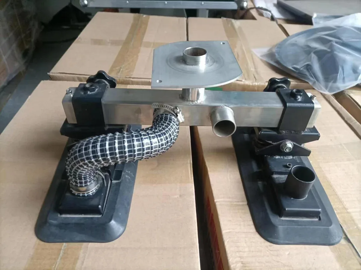
Check the approved connection, seals, mechanical retention and vacuum connections after a head change. For multiple pads, each intended contact and connection matters. The presence of two or four pads does not establish that all are connected, seated or permitted for that workpiece.
The package itself
Compare the actual filled package with the one used to approve the installation. A different paper or film, seam position, taped area, perforation or more flexible panel can change the contact. Check the package’s ability to carry its contents as well as the face touched by the suction head.
A fault limited to one batch points the investigation toward those differences, but does not by itself prove the packaging is at fault. A marginal machine condition may become apparent only on the more demanding package. Retain the batch information and the maintenance history together.
For a change of product or packaging, use the bag and carton station selection guide to define the proposed task. The original acceptance of one package should not be carried over to another without review.
6. Distinguish a travel limit from weak lifting
“It will not lift high enough” needs a different record from “it will not leave the pallet.” Establish whether the machine stopped at a consistent geometric limit or whether its behaviour changed during a previously successful movement. Do not pull on the head or stretch the tube to obtain extra reach.
For example, ETJSQ-V100-30 lists a 2,500 mm lifting-tube length and a 1,700 mm lifting stroke. Those measurements describe different things. Neither number, by itself, states the maximum height at which a carton can be placed in a particular installation.
The available position also depends on the suspension height, the head and its connection, the workpiece dimensions, and the clearance at pickup and placement. A wider or taller replacement head can alter that geometry even when the nominal load is unchanged.
- Record the lowest pickup and highest placement positions using a consistent reference, such as the workpiece contact face.
- Include the head/tooling below the lifting tube and the space occupied by the workpiece.
- Record obstacles and the required handle position at the difficult end of the task.
- Compare the installed arrangement with its approved drawing and the previously accepted transfer.
Increasing a vacuum setting does not create additional approved stroke. If the required task lies outside the installation’s working envelope, it needs a configuration or layout review.
7. Use the timing of the change to narrow the review
The following are reasoning examples, not reported customer incidents or permission to repeat a faulty lift.
After a filter change
Observation: the same approved package became difficult to lift immediately after service.
Review first: the fitted element, cover/seal, hose reconnection and the work actually performed. The timing gives a starting point; it does not prove the filter is the only cause.
After a head change
Observation: the unloaded head now rises to its upper position and the new package behaves differently.
Review first: the approved head–control–tube combination, suspended tooling, connections and unloaded setup. Do not adjust around an unapproved combination.
At the highest placement point
Observation: the load leaves the pallet but cannot reach the new stacking position.
Review first: stroke, suspension height, tool dimensions and obstructions. Include any change in indicated vacuum or contact; a geometric limit and a flow problem are different branches.
Questions that commonly cause confusion
Why can the head feel attached while the load stays on the pallet?
Contact does not establish sufficient lift or an approved load condition. Check the actual package against the appropriate surface-dependent rating, the installed head/control combination and the source and flow path. The supporting pallet can also mask the difference between attachment and a successfully completed lift.
Does an empty head rising by itself mean there is too much vacuum?
It indicates an unloaded-position/control issue to investigate, not a complete diagnosis. Easytech’s fault table directs attention to unloaded suspension setup and filtration. Identify the installed assembly and any change before attributing the behaviour to a setting.
Should a larger blower fix a porous bag that will not lift?
It cannot be assumed. The head, package, controls, filtration and lifting unit must work as an approved combination. Changing the source is a system change; it is not a way to exceed the applicable load rating.
Can a non-return valve guarantee a fixed holding time after power loss?
No universal time can be inferred from the presence of the valve. Response depends on the actual equipment, contact and condition. Follow the delivered emergency procedure; do not perform a loaded power-cut experiment to establish a time.
8. Send a fault record that can lead to a decision
“The suction is weak” leaves the service team to guess both the equipment and the event. A short, structured record is more useful than a new video of an unsafe operation.
Vacuum tube lifter fault record
- Equipment: machine model, serial/identification label, source label and control-head photographs.
- Installed tooling: head/pad arrangement, connection, and any recent replacement.
- Workpiece: filled weight, dimensions, packaging material, usable contact face and batch changes.
- Exact symptom: no contact; contact but no rise; empty-head hover problem; loss of grip while lowering; or insufficient travel.
- When it happens: unloaded/loaded, pickup/lift/lower/place, first use/after service/after a product change.
- Available indications: existing gauge reading with location and unit, alarms and source behaviour. Do not add instruments or create a test without the service procedure.
- History: last successful task, maintenance performed, setting changes and the applicable manual revision.
- Current status: how the equipment has been made safe and what remains out of service.
Download the fault record PDF — English
Take photographs of labels and components only when the equipment is safe to approach. Send the record through Easytech technical contact. It allows the next step to be a specific parts, configuration or service decision.
Returning the machine to use
Closing the fault means recording the identified cause, the approved repair or configuration correction, and the prescribed checks performed before return to service. Restored movement alone does not verify grip, release, protective functions and compatibility with the intended package. Keep the final record with the installed equipment’s instructions.
Technical basis and further reading
This guide draws on Easytech tube-lifter operating documentation, the 2026 tube-lifter catalog and the current model/control specifications linked above, and the manufacturer’s clarification of the loaded-hover adjustment. Photographs show real equipment and components from Easytech’s archive; they are identification examples, not images of diagnosed failures. Operating settings and service acceptance remain specific to the delivered assembly.