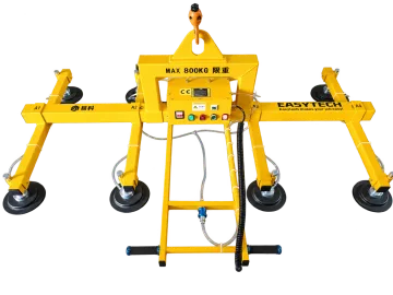
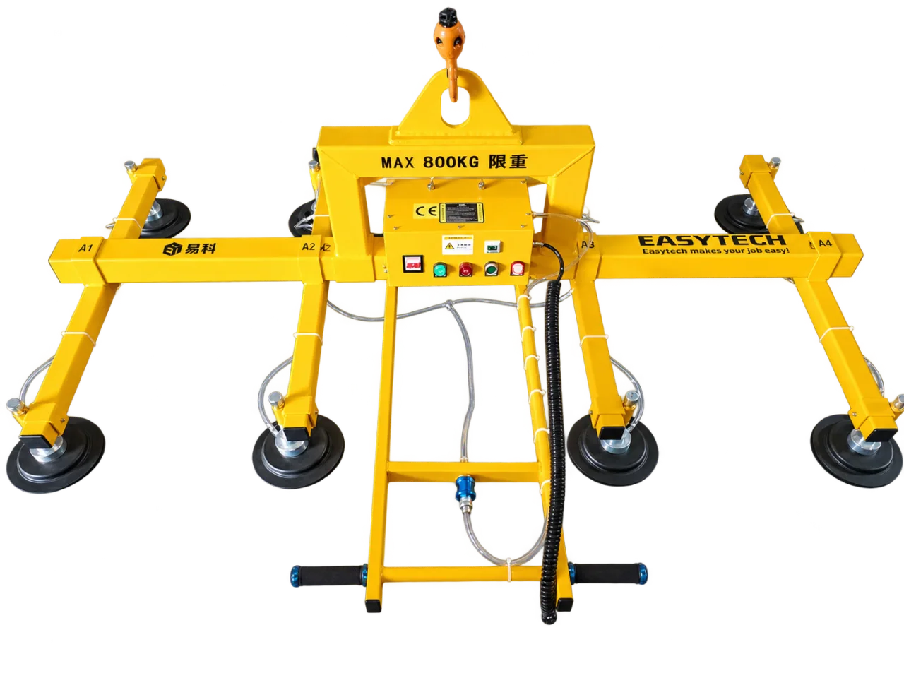
Calculate the ideal static force
Use F = Δp × A, with pressure difference Δp in pascals and effective sealed area A in square metres; the result F is in newtons. The effective area is the area enclosed by the working seal, not automatically the area calculated from the outside diameter.
For illustration only, a 40 kPa pressure difference across 100 cm² gives 40,000 × 0.01 = 400 N of ideal static normal force. This example is not a product specification or a permitted payload. It contains no allowance for dynamics, direction, leakage, the supporting structure or the approved design factors.
Quantity | Meaning | Unit conversion |
|---|---|---|
Pressure difference | Ambient pressure minus pressure inside the sealed area | 1 kPa = 1,000 Pa |
Effective area | Area enclosed by the working seal | 1 cm² = 0.0001 m² |
Theoretical force | Ideal force normal to the contact face | Pa × m² = N |
Why this does not produce a safe working load
A real lifting arrangement must also address friction in the load direction, acceleration, centre-of-gravity offset, deformation and the approved safety margins. Leakage can prevent the assumed pressure difference from being maintained. More nominal cup area cannot correct every one of those conditions.
The published equipment rating and its operating conditions govern selection. Do not multiply a theoretical force by pad count and replace the machine rating with that result. Load distribution, structure and vacuum-circuit arrangement must be assessed for the complete configuration.
Use the calculation to ask better questions
Buyer question | Evidence to request |
|---|---|
What area is effective? | The specified cup/seal geometry in its working condition. |
Which vacuum value applies? | The approved operating indication or limit for that configuration. |
Is the face vertical or horizontal? | Permitted orientation and the corresponding design assessment. |
Will the surface leak? | Representative material trial and the selected vacuum source. |
Are the pads evenly loaded? | Pad arrangement, workpiece geometry and support assessment. |
What is the permitted load? | The complete equipment specification and applicable operating documents. |
Apply it to an Easytech selection
Send the workpiece drawing, weight, orientation, surface and required movements. We use those inputs to identify an equipment configuration for review. The model PDF remains the reference for published product values; this theoretical example does not amend it.
Check units before interpreting the result
Illustrative input | Ideal normal force | Interpretation |
|---|---|---|
40 kPa over 100 cm² | 400 N | 40,000 Pa × 0.01 m². |
40 kPa over 200 cm² | 800 N | Doubling effective area doubles this ideal result. |
20 kPa over 100 cm² | 200 N | Halving pressure difference halves this ideal result. |
These are ideal static examples, not equipment capacities. Converting newtons into an equivalent gravitational mass would still omit friction, motion, offsets, leakage and the required design assessment. Therefore this page deliberately does not turn the examples into a permitted lifting weight.
Relate the calculation to a published configuration
ET-SM-C2000-3M — Extended-Range Sheet Metal Vacuum Lifter — The adopted 2,000 kg sheet arrangement has alternatives of 20 × Ø200 mm or 16 × Ø250 mm pads. The published complete-system rating comes from the configuration, not from replacing effective area with outside pad diameter in this formula.
Technical reference: Schmalz suction-cup design
Find the correct replacement cup · Compare sheet lifting configurations