Separate the gripping system from the lifting system
Function | What it does | Buyer question |
|---|---|---|
Vacuum generation | Creates the pressure difference needed at the contact. | Which source and utility supply are specified? |
Suction head or pads | Forms the interface with the workpiece. | Will the approved contact suit this material and geometry? |
Lifting mechanism | Raises and lowers the gripped load. | Is this a tube-lifting unit, hoist-supported frame or another arrangement? |
Positioning | Moves, tilts or rotates the assembly as specified. | Which movements are included and how are they controlled? |
Indication and controls | Supports the prescribed gripping, monitoring and release sequence. | Which indication, alarm and release functions are documented? |
Understand the two common formats
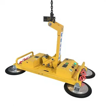
In a tube-lifting format, the lifting unit and head are selected together for the handling cycle. In a suspended vacuum-frame arrangement, gripping and the supporting hoist/crane are separate parts of the complete assembly. Choosing the right head does not eliminate the need to check usable stroke or the supporting lifting equipment.
Why the workpiece matters
A surface must suit the approved contact arrangement. Roughness, porosity, folds, holes, coatings or a weak lid can change the result. Long or flexible workpieces also need a suitable support pattern. A material trial is especially useful when packaging or surface conditions vary.
What to look for on a model page
- The published rating and any configuration or orientation conditions.
- Pad/head dimensions and the workpiece contact arrangement.
- Vacuum source and required utilities.
- Lifting, tilt and rotation functions identified separately.
- Equipment weight, support/mounting and available working-envelope information.
- A matching PDF and clearly labelled product/reference images.
Trace three actual equipment formats
Example | What grips | What lifts or positions |
|---|---|---|
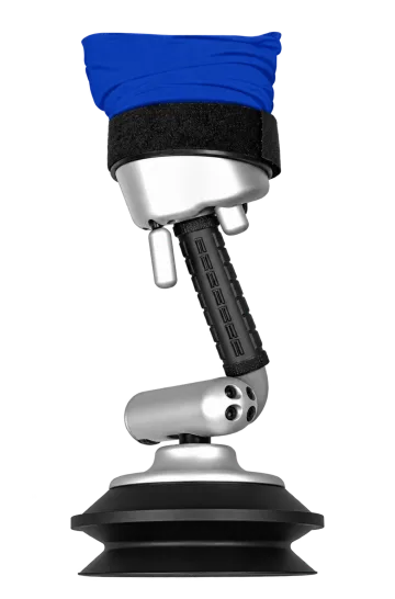
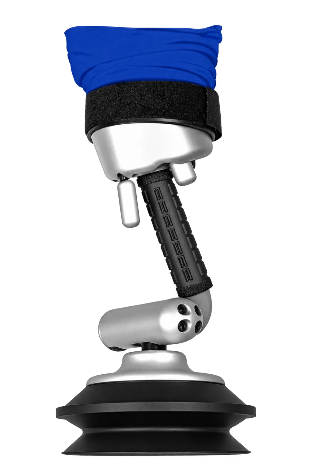
Workpiece-matched suction head. | Vacuum lifting tube with controlled vertical movement; a support carries the assembly. | |
H-frame suction pads. | A separate crane/hoist provides lift; this frame lists manual tilt and rotation. | |
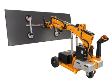
Robot vacuum head. | The mobile chassis and powered positioning functions serve the installation task. |
This distinction explains why a vacuum-pump specification cannot describe the entire handling machine. It also explains why replacing a suction head does not increase the crane, arm or tube-lifter capacity.
Stored vacuum, an alarm and independent circuits are different
A reservoir stores a volume under vacuum, an alarm indicates a defined condition, and a circuit description identifies the arrangement of vacuum paths. One feature does not prove the others are present. Read the model’s own system entry and request the applicable instructions; do not infer a reserve holding time from the presence of a reservoir.
Compare vacuum lifting formats · Bag and carton tube lifters · Theoretical suction force