
This illustrated example is the modular frame shown in the supplied 600 kg assembly sheet. It does not identify every lifter or establish your machine’s capacity, fastener torque, pad layout or electrical supply.
Recognize the assembly sequence
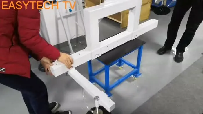
Match the delivered drawing and components
Find the machine model/serial label, assembly drawing, specified fasteners, control module and pad/beam layout. Stop if a part is missing or its purpose is unclear. Similar appearance does not establish compatibility.
Identify the crossbeams and hole orientation
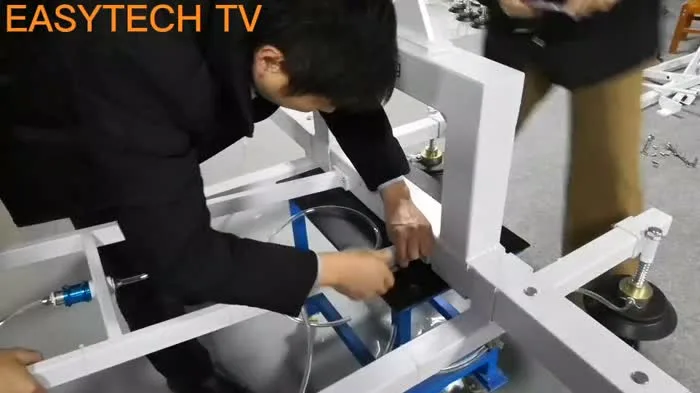
The supplied assembly sheet specifically calls out the direction of crossbeam holes. Match the delivered drawing before fixing a beam; reversing a part can change where later brackets and handles attach. The example photograph is not a substitute for hole dimensions or locking instructions.
Identify the control-box base and module
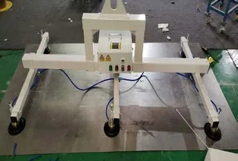
The sheet shows the base fitted before the control box. Check the approved mounting and retention arrangement. Do not energize a loose module or infer tightening torque from the video.
Identify the handle and accessible air path
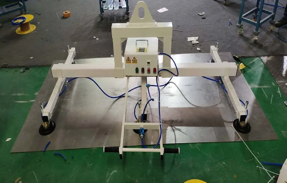
The final illustrated step calls out handle direction. Compare the handle, hose routing and controls with your own drawing. Ensure hoses and cables will not be trapped or pulled through the permitted movement.
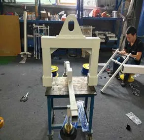
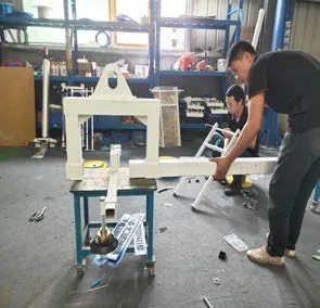
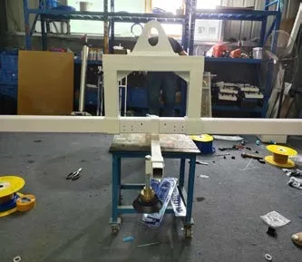
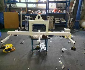
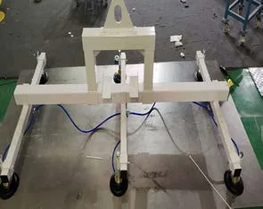
Seven photographs from the actual assembly sheet
These are the original embedded photographs, with English captions. The first six source photographs have limited resolution; the original detail has been preserved. They establish the illustrated order and component positions, not fastening torque or a commissioning pass.
Do not confuse a vacuum connection with compressed-air supply
An electric vacuum-source module and a pneumatic vacuum generator require different supplies. One existing electric-machine manual identifies a power connection and a vacuum output; the pneumatic manual instead calls for compressed air. Therefore, do not connect shop air merely because a fitting accepts an air hose.
Read the actual module labels and machine diagram. Electrical connection, protective measures and supply checks belong to qualified personnel. A connector that physically fits is not proof of the correct voltage, polarity, pressure or purpose.
Before the first lift
- Confirm the actual approved configuration, workpiece and lifting arrangement.
- Verify specified fasteners and retainers, pad connections, hose routing and control identification.
- Complete the machine-specific commissioning and warning checks with competent personnel.
- Use the supplied operating procedure for attachment, readiness, movement and release. Release only after the workpiece is fully supported.
Pre-use and maintenance checks · Report a missing or unclear assembly detail