Handle reach and permitted combination
A handle dimension or compatible-load figure is not a new rating for the installed tube lifter. Check the control position at both pallet extremes and confirm the head, handle, lifting unit and source as one assembly.
Compare the published configuration
Selection point | |||
|---|---|---|---|
Series maximum compatible load | 250 kg | — | — |
Handle length options | — | 350 / 550 / 750 mm | — |
Operating height range | — | 1700 mm | 1700 mm |
Lifting height configuration | 1700 / 2500 mm | — | — |
Equipment and intended application
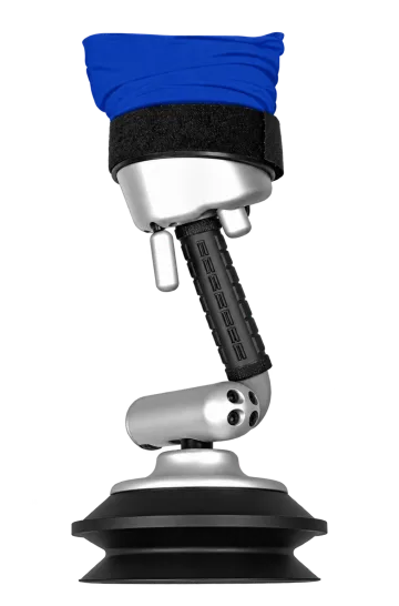
An extended, curved two-hand control with grip/release controls at the handle ends and a quick-release valve. It is intended to make lower pickup positions accessible.
Choosing this component
The catalog lists separate lifting-height configurations. Select one compatible tube/handle combination; the handle-series maximum is not the rating of every tube fitted to it.
Application and integration requirements
Topic | Details |
|---|---|
Identify the installed unit | Record machine model and serial number, component markings and clear photos of the connection. Compare dimensions, seal profile and fixing geometry. |
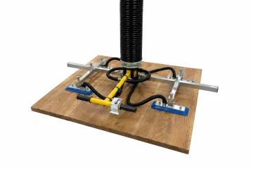
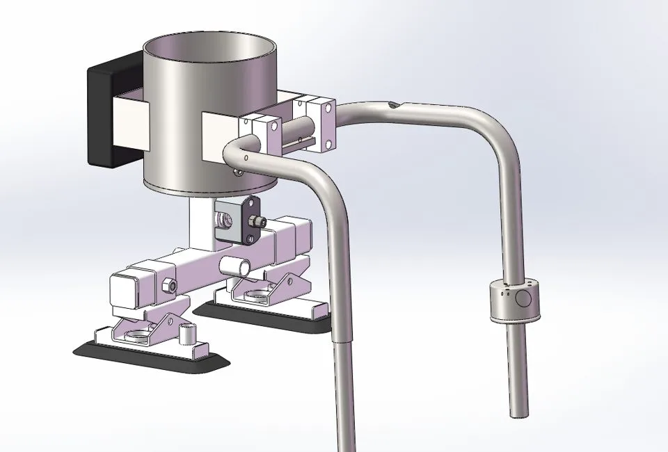
Match its function | A suction head, lifting tube, supply hose, valve and filter occupy different positions in the system. Similar-looking parts may have different mechanical or airflow duties. |
Validate the assembly | After replacement, check retention, sealing and functional response. A different head can change suspended mass, load balance and permissible workpiece geometry. |
Installation, inspection and service checks
Topic | Details |
|---|---|
Replacement preparation | Support the load, shut down and isolate the relevant energy source before disconnection. |
Installation | Match the approved connection and sealing arrangement; do not force a mismatched flange, thread or hose onto the machine. |
Return to service | Check tightness and controls, then perform the prescribed functional checks. Do not put a repaired component straight into loaded production. |
Troubleshooting priorities
Topic | Details |
|---|---|
Unexpected grip, motion or control behaviour | Stop with the workpiece supported. Inspect the affected connection, contact area and power or air supply, then follow the installed equipment instructions before returning to service. |
Replacement does not fit or changes performance | Check the component identity and system configuration. Do not modify interfaces or bypass protective functions to make a substitute fit. |
Frequently asked questions
Can Type C be fitted to any vacuum lifter?
No. Match Type C to the machine identification, connection, dimensions, operating conditions and the intended gripping task. A similar appearance or part diameter does not demonstrate compatibility.
Information for component selection
- Identify the installed lifting unit, model and serial number, and include photographs of the existing component and its connections.
- Record the component dimensions, mounting points, connection type, material and any visible markings.
- Describe the handled material and operating conditions, or the fault that led to replacement. A part that fits physically still needs to match the system duty.
Document scope
This product specification supports equipment selection and project definition. It includes the model data and application guidance presented on the product page. The operating instructions supplied for the actual machine govern commissioning, testing, maintenance procedures and safe use; this specification does not replace them.