
When we discuss a new handling station, we want to understand the complete job: what we are lifting, how we will grip it, where it needs to go, and what air is available at that location. Those details belong in the same conversation. They help us avoid specifying a suitable arm and attachment, then discovering at installation that the final air connection cannot support the task.
You do not need to become a pneumatics engineer to prepare a useful enquiry. Below, we explain which information matters, what the filter and regulator actually do, and how to agree the installation responsibilities before the machine arrives.
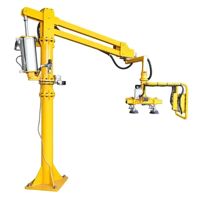
Start with the whole machine, including the gripping tool
The air requirement belongs to a particular machine and attachment. Two manipulators with similar arms can have different demands because their lifting mechanisms, travel, controls and tools differ.
On a rigid-arm manipulator, the lifting cylinder and linked arms provide the vertical movement. A wire-rope arrangement raises and lowers a suspended handle or tool. At the working end, the load connection might be a hook, a pneumatic clamp or a vacuum head. Each arrangement needs its own supply assessment.
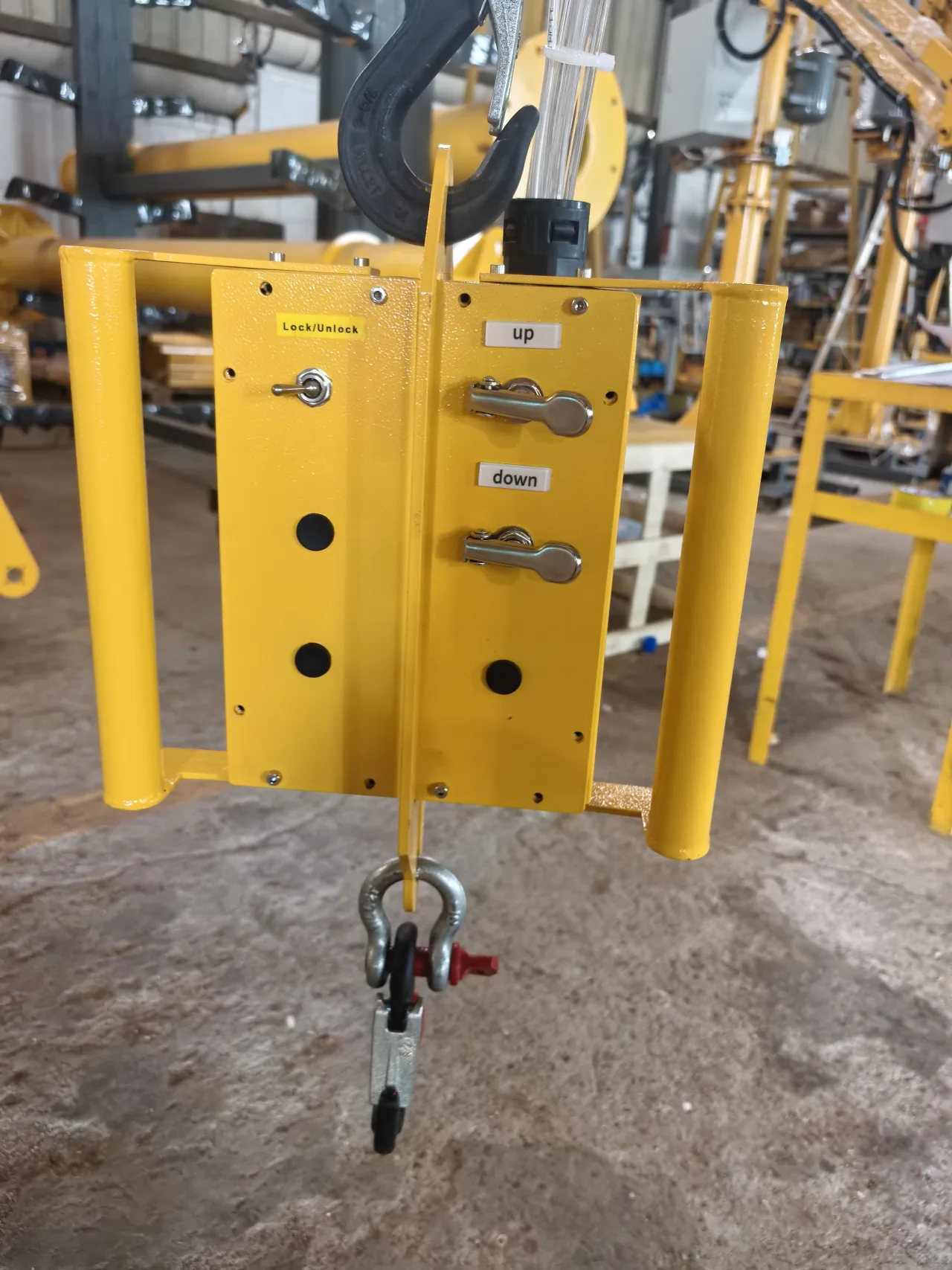
Our pail-handling project, for example, uses a hook below a control handle. The operator also controls the arm brakes. A hook itself does not need a stream of air to create suction. A vacuum-equipped configuration may use compressed air to generate vacuum, in addition to the air required for movement. The selected vacuum generator and its control cycle then become part of the demand calculation.
This is why we ask about the attachment early. “A pneumatic manipulator for this weight” does not yet describe everything the air supply must serve. Tell us whether the job includes gripping, tilting, rotation, braking or a change of tool, and which actions must happen together.
Pressure tells us one thing; airflow tells us another
Pressure describes the compressed-air condition at a measurement point. Airflow describes how much air is delivered over time. Both are needed to select the supply.
Think about the difference between waiting and moving. While a machine is idle, a restricted line may eventually reach the indicated pressure. During an action, air must pass through that same line fast enough to serve the equipment. An acceptable idle indication therefore does not establish adequate delivery during a lifting cycle.
A compressor's motor power is another separate figure. A motor rating in kW or horsepower does not, by itself, tell us the air available at the manipulator at its required pressure. For compressor selection, obtain the delivered-air rating at the intended operating condition and have the compressed-air supplier check the site's total demand.
Compare units before comparing quotations
Pressure may be stated in MPa, bar or psi. As a unit conversion, 0.6 MPa equals 6 bar, approximately 87 psi. That conversion does not set the operating pressure for your manipulator. Use the pressure requirement and permitted limits for the supplied configuration, and keep the measurement location with the value.
Flow figures also need their basis. A number expressed as litres per minute at line pressure cannot be compared directly with a number expressed as free-air delivery or normal litres per minute. Ask the suppliers to state the reference conditions and put their figures on the same basis before deciding that one compressor or connection is sufficient.
Information in the quotation | What it helps you decide |
|---|---|
Supply pressure and test point | Whether the site can provide the specified condition at the machine connection. |
Air consumed per cycle | The demand associated with the proposed lifting and tooling sequence. |
Peak demand | Whether the branch and local components can support the busiest part of the cycle. |
Units and reference conditions | Whether the machine demand and compressor delivery figures are comparable. |
Plan for the working cycle, not just a pressure gauge
A useful cycle description starts at pickup and finishes when the equipment is ready for the next workpiece. Include approach, attachment, lifting, transfer, placement, release and return. Mark any operation that continues while the operator waits.
This gives us a much clearer specification than an estimated number of lifts per hour alone. A station that makes short bursts of movement can have a modest average demand and a higher momentary requirement. A vacuum generator that remains active during a hold adds a different demand from a clamp that operates at particular stages. Confirm which behaviour applies to the selected circuit.
Ask for consumption against that described cycle. If the supplier provides a volume of free air per cycle, multiplying it by cycles per minute gives the corresponding average flow. Include any separately specified continuous demand without counting it twice. Keep all figures on the same reference basis.
That calculation is useful for estimating average demand; the peak requirement still needs assessment. The machine must receive adequate supply when the necessary functions operate, including when neighbouring equipment uses the same branch. A quiet demonstration before production starts is not the same operating condition as the busiest shift.
For a shared system, tell the air-system designer which nearby machines operate simultaneously, whether there are large intermittent users, and whether another workstation is planned. For a dedicated compressor, include the manipulator's complete cycle and any other intended air users. That information supports a meaningful capacity recommendation instead of a guess from motor size.
Follow the air to the actual installation point
The final connection deserves attention even when the factory has a substantial compressor installation. Record the route from the existing supply branch to the proposed machine: approximate length, pipe or hose size, quick couplings, isolation points, filters and regulators. A simple annotated photograph is often enough to start the discussion.
Restrictions at hoses, couplings, filters and regulators can cause pressure loss during flow. The US Department of Energy's compressed-air sourcebook recommends assessing these components under the required operating conditions. Its pressure-drop guidance also explains why raising compressor pressure can conceal a local restriction while increasing demand elsewhere.
For your project, have the responsible technician assess the proposed connection while the relevant production equipment is operating. Record where pressure was measured and what was running. Keep the result with the installation information so that the factory air-system supplier and the machine supplier are discussing the same point.
We also need to know where the connection sits relative to the machine. A hose that reaches the column in its parked position may take a different path when the arm moves. Plan the supply route, service access and protection from surrounding equipment together. The commissioning check should cover the agreed working envelope, with the machine operated according to its installation procedure.
Know what the filter-regulator assembly can do
The air-preparation assembly in our pneumatic-manipulator instructions combines pressure regulation and filtration, with a pressure gauge and a bowl that collects separated liquid and contamination. These parts have different jobs. Understanding them makes both installation and routine care easier.
The regulator controls downstream pressure
The regulator reduces and controls the pressure supplied to its downstream circuit within the unit's operating capability. It cannot create additional upstream air capacity. Turning its adjustment higher is therefore not a general solution to a supply shortfall, and it does not increase the machine's approved lifting capacity.
Leave the machine's established pressure and motion settings to the applicable commissioning or service procedure. When a setting needs investigation, the technician needs the machine identity, circuit and specified condition—not a setting copied from a photograph of another manipulator.
The gauge needs a location and an operating condition
A gauge shows pressure at its connection. Label that location in the handover record: before the preparation assembly, after the regulator, or at another designated point. Also record whether the reading was taken at rest or during the prescribed operating check.
This small detail makes later support much more useful. “The gauge shows the required pressure” can mean several things. “The downstream gauge remained within the specified range during the agreed commissioning cycle” describes a particular check that can be compared with later observations.
The filter and collecting bowl need access
The assembly separates contamination according to the fitted filter's capability, and the bowl collects liquid that needs to be drained. Keep the bowl visible and leave room for the prescribed service work. Hiding it behind a guard or placing it where maintenance staff cannot reach it creates a problem that is easy to avoid on the layout drawing.
Our instructions call for clean, dry compressed air and for collected liquid to remain below the bowl's marked limit. Set the inspection and drainage routine from the actual air quality, usage and component instructions. The bowl should be checked before accumulated liquid reaches that limit.
Drainage and cleaning are different maintenance operations. Follow the fitted component's procedure for each. Isolate the equipment and release residual pressure as prescribed before dismantling or maintenance; never loosen a pressurised bowl or connection. The machine and any load must first be in the safe condition required by its instructions.
A collecting bowl is not a complete drying system
A filter bowl collecting liquid does not prove that all water vapour or oil contamination has been removed from the supply. Air treatment must suit the incoming air and the equipment's required quality. Drying, particle filtration and oil removal may require different components.
Ask the site air-system supplier to assess treatment at the machine connection, including the effect of the distribution system and workshop conditions. An empty bowl is an observation about collected liquid, not a measurement of the entire air-quality specification.
Do not add an airline lubricator by habit
An air-preparation unit is sometimes called an FRL: filter, regulator and lubricator. That abbreviation can be misleading when ordering replacements or preparing a new branch. Our pneumatic-manipulator instructions specify clean, dry air without oil or moisture, and describe a filter-and-regulator assembly. They do not give permission to add oil to that airline.
Match the preparation equipment to the supplied machine's requirements. If an existing branch serves tools that use lubricated air, disclose that arrangement before connecting the manipulator. The air-system supplier needs to check whether the branch and its treatment are suitable.
Mechanical lubrication elsewhere on a machine is a separate maintenance task. An instruction to lubricate a mechanical part does not mean that oil should be introduced into the compressed-air inlet. Keeping those two tasks separate avoids a surprisingly easy procurement mistake.
Agree who supplies each part before delivery
A project can be delayed by a simple gap between responsibilities: the site expects a ready-to-connect hose, while the equipment scope ends at an inlet fitting. Resolve that boundary in the order and installation layout.
Installation item | Agree before the machine arrives |
|---|---|
Air-supply connection | Its location, fitting or thread, and the required supply condition at that point. |
Final branch, hose and couplings | Who selects and supplies them, their route, and how they will accommodate the working envelope. |
Air preparation | Which components arrive with the machine and which treatment belongs to the site system. |
Isolation and service access | The agreed isolation arrangement and access for inspection, drainage and maintenance. |
Commissioning | Who performs the prescribed checks, what conditions will be tested and who receives the handover. |
The correct inlet and outlet direction on an air-preparation component matters. Our installation instructions also use matching marks for reconnecting air lines. Preserve those identifications and follow the supplied arrangement. A fitting that can physically be connected is not proof that two lines serve the same function.
Keep the selected tool in this discussion. A later change from a hook to a powered clamp or suction assembly may affect the controls, connections and air demand, as well as the load-handling assessment. Bring proposed changes back to the machine supplier before treating them as interchangeable accessories.
What we want to see at commissioning
Commissioning should show that the supplied station can perform its agreed task with the site's actual services. The installer should use the approved procedure for the delivered configuration, rather than improvise a loaded test.
The air-related handover should identify the machine and tool, the installed preparation components, the supply connection and the applicable pressure requirements. Record the observed supply condition during the prescribed cycle, the condition of connections and hose routing, and any outstanding action that prevents release for use.
The operating checks also need to cover the relevant grip, release, motion and protective functions. Making an unloaded arm move is only one observation. It does not establish that the attachment is suitable for the workpiece or that the complete handling sequence has been accepted.
Supply interruption needs particular care. Different lifting and gripping arrangements have different protective behaviour. Recovery must follow the supplied procedure; do not disconnect the air to experiment with a suspended load. We explain those distinctions in our guide to power-loss protection.
Once accepted, keep the settings and handover record with the equipment. They provide a useful baseline if the machine is moved to another branch, the tool changes or a new nearby air user is installed. If there is already a lifting or lowering fault, use the pneumatic manipulator troubleshooting guide to organise the observations for service.
Questions we would settle before ordering
Can we use a small portable compressor?
Possibly, if its delivered-air capacity, pressure range, duty capability and air treatment meet the complete machine requirement. Check the selected compressor against the defined operating cycle and peak demand. A receiver size or advertised maximum pressure alone is not enough to make that choice. Ask the compressor supplier to assess the actual application before purchase.
Does a pneumatic manipulator need an electrical connection?
Check the complete configuration. Compressed air may power the lifting mechanism while controls, sensing or other accessories have their own electrical requirements. Put both pneumatic and electrical interfaces in the agreed equipment scope. The word “pneumatic” does not settle every utility connection.
Can the same supply be used after moving the machine?
Recheck the new installation point. The nominal factory supply may be unchanged, while branch length, couplings, nearby demand, hose routing and treatment differ. Treat the new position as an installation change and complete the prescribed checks before returning the equipment to work.
Send us the task and the available air supply
For an initial enquiry, send a workpiece photograph, its weight if known, and the pickup and placement positions. Tell us which movements you need and whether compressed air is already available nearby. If you have a photo of the intended connection or a supply specification, include it.
We can then discuss the manipulator and attachment together, identify the utilities to confirm and put the installation boundary into the proposal. You can start that conversation before every technical detail is settled.
Explore our industrial manipulators or tell us about your handling task.