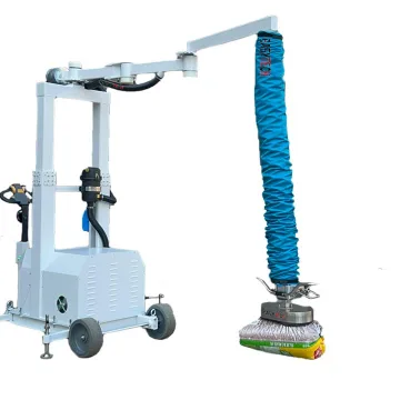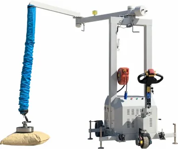
A mobile tube lifter must fit two different spaces: the place where it lifts and the route used to move it there. A station can reach every carton on a pallet yet be too tall for the doorway. It can pass through the door yet leave too little space for the operator when the arm opens.
Start with the actual load and suction head, then check working height, horizontal coverage, transport dimensions and power supply together. “Mobile” alone does not tell you whether the column lowers, how the base moves or what powers the vacuum source.
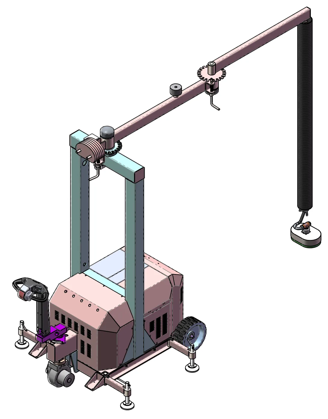
Choose the kind of mobility you actually need
Need | Arrangement to examine | Question that decides the fit |
|---|---|---|
Move occasionally between nearby stations | Repositionable base | How is the unloaded station moved, parked and supported for lifting? |
Pass under low doors or services | Height-adjustable column and a defined parked arm position | What is the maximum height of the complete equipment in transport condition? |
Move frequently over a longer route | Powered-travel base | Can the base negotiate the route, and how is the arm secured? |
Work away from a suitable socket | A configuration with battery-powered vacuum operation | Which functions use the battery, and can the agreed duty cycle be completed between charges? |
Powered travel and battery-powered vacuum are separate functions. Ask for both to be identified in the selected configuration. Similarly, adjustable support feet level or support a base; they do not mean that its column telescopes.
Compare the current Easytech mobile arrangements
Model | Selection facts | Check before choosing |
|---|---|---|
60 kg rated load; 3,000 mm jib; 250° rotation; steel counterweight base and adjustable feet; 10 m cable reel. | Space for the base, working supports and cable route. Do not treat the adjustable feet as a lowering column. | |
60 kg rated load; telescopic column and bending-tube arrangement; forklift repositioning with the jib locked. | Agreed transport and operating heights, forklift access and the lock sequence for the supplied station. | |
60 kg rated load; powered travel; articulating arm; 2,100 mm folded clearance; mains/battery options. | The exact transport envelope, selected power arrangement, charging access and route conditions. |
The rated load does not establish that a particular sack, carton or panel can be gripped. Surface leakage, packaging strength, suction-head selection and the complete equipment configuration still have to suit the load. The layout illustrations in this guide show arrangement choices; use the selected model drawing for final dimensions.
Measure the working station from one floor datum
- Mark the lowest pickup surface, including the last layer on the pallet.
- Mark the highest placement surface, including the top layer of the completed stack.
- Add the actual package height and the space occupied by the suction head and control assembly.
- Locate the lowest overhead obstruction over the whole movement: beam, duct, light, sprinkler or doorway.
- Check the operator's hand position at both height extremes, not just at a comfortable middle position.
Do not subtract two catalogue heights and call the result usable lift. Tube length, lifting stroke, head height and column adjustment describe different dimensions. A taller column may provide overhead clearance but does not automatically provide more usable stroke. Ask for a side view showing the complete head at the lowest pickup and highest placement positions.
Draw the full movement, not just the arm radius
On a top view, mark the base, every pallet corner, the machine opening and the operator's standing space. Trace the suction head from the farthest pickup to the final placement. Then check the intermediate positions: the arm elbow, package and handle may sweep across an obstruction even when both end points are reachable.
An articulating arm can help work around a station, but it does not remove the base footprint. The operator also needs a route that does not require stepping over supports, cables or pallets. If access to the last row depends on leaning across the stack, review the handle and pallet positions before increasing arm length.
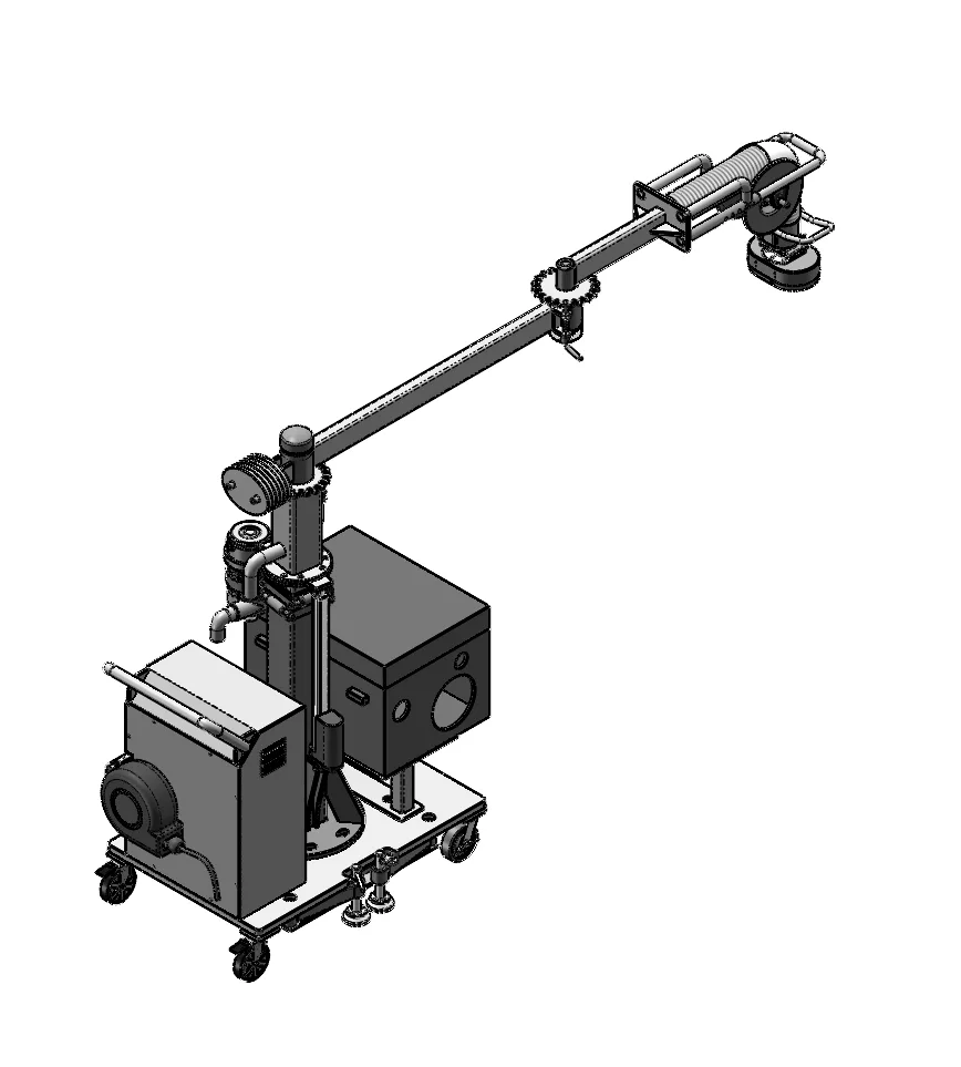
Check the move between stations separately
Measure the narrowest doorway, the lowest overhead opening and the tightest turn. Include the equipment's base, wheels, controls, stored head and projecting arm sections. A nominal folded height alone cannot prove that the station will turn into a corridor.
Review floor joints, thresholds, ramps and the route's surface with the equipment supplier. Do not assume a powered-travel base is suitable for a slope or uneven outdoor surface. Establish the permitted transport condition and floor requirements for that configuration.
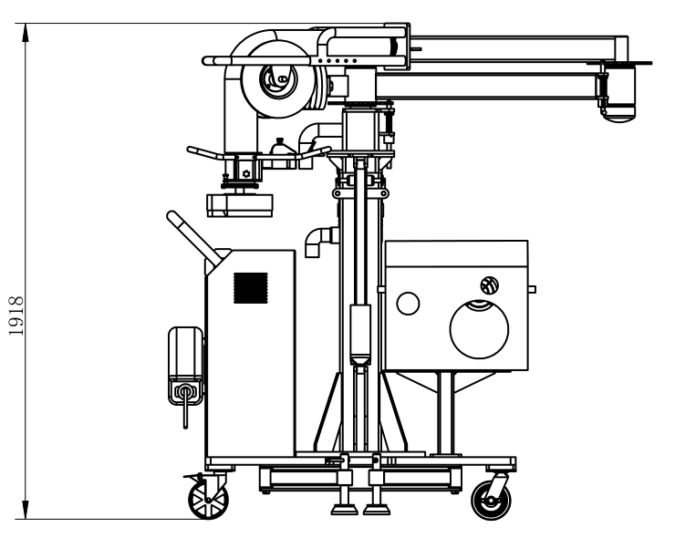
Reposition the station only in its prescribed transport state, without a suspended workpiece. The supplied instructions must define the arm lock, head storage, supports and movement method. At the destination, complete the prescribed parking and support procedure before lifting. Mobile equipment is not automatically a load-carrying vehicle.
Power, cables and charging can decide the layout
For mains operation, identify the available supply and the cable path at every station. A cable reel length is not a working radius: the lead must reach the connection along a protected route without crossing the operator's movement or being trapped under the base.
For battery operation, provide a realistic pattern of lifts, idle periods and station moves. Request an operating-time assessment for the chosen vacuum source and travel system, together with charging time and the charging location. Do not size a shift from the battery label alone. If the application changes between porous sacks and sealed cartons, include both in the evaluation.
Use an acceptance trial that represents the job
Trial | What to observe |
|---|---|
Lowest and farthest pickup | Head reaches the contact face; the operator can control it without stretching over the load. |
Highest placement | Package, head, handle and tube clear the overhead space throughout placement and release. |
Full route with the agreed load | Arm, package and operator clear obstructions; the package remains stable on the selected head. |
Repositioning without a load | Specified locks and supports work; the complete station passes through the surveyed route. |
Repeated work with actual packaging | Grip, release, filter condition, operator access and utilities remain suitable over the agreed trial. |
Record any failed position with a photograph and the floor-to-contact height. A useful correction might be a different head, handle or pallet position rather than a larger lifting unit. For package preparation and cycle observations, use the bag and carton workstation guide.
What to send for a mobile-station proposal
Send a top view, a side view, the minimum and maximum package weights, packaging samples or clear surface photographs, the transport route measurements and the available utilities. A simple marked-up photograph is enough to begin. Include the difficult position—the lowest pallet layer, far corner or machine opening—so the proposal solves the part of the job that currently slows you down.
Start with the model links above if an arrangement already looks suitable. For the supporting structure and installation interfaces, see jib-crane installation planning.