
A cracked or torn lifting tube needs more than a new length of hose. The tube, end adapters, clamps, sealing materials and cover form an assembly. The replacement must match that assembly, and the repaired lifter needs a controlled functional check before it returns to work.
This guide helps an owner prepare the repair and a qualified technician inspect the interfaces. The photographs show a clamp-and-cover construction. If your lifter uses different adapters or fasteners, use its own assembly instructions; do not copy the pictured joint onto it.
First identify which tube needs replacement
Part | Where it is | How to identify it |
|---|---|---|
Lifting tube | Between the upper suspension/rotation unit and the control head | Expands and contracts during lifting; record its markings, diameter and both end connections. |
Vacuum supply hose | From the vacuum source to the lifting assembly | Routes the airflow; record its own bore, routing and connectors separately. |
Protective cover or sleeve | Outside a tube or joint | May conceal the fastening underneath. A damaged cover does not by itself identify damage to the lifting tube. |
Do not order by colour alone. A similar-looking hose can have a different construction or end connection. Photograph the equipment nameplate, the complete suspended assembly and both joints before dismantling. Identify the part through the machine serial number or the original parts list wherever possible.
Decide whether the fault really points to the lifting tube
Visible cracks, slits or holes in the lifting tube are a reason to remove the equipment from lifting service and arrange the specified replacement. If the tube looks intact but the lifter is weak, first distinguish a tube leak from a loose joint, damaged pad seal, obstructed filter or supply-hose problem. Follow the tube-lifter fault diagnosis instead of replacing parts at random.
Do not patch a damaged lifting tube with the tape shown around an end joint. Joint-sealing tape and a damaged tube wall are different problems. A cover placed over a defect does not restore the tube.
Match the complete replacement before opening the joints
- Machine model, serial number and the installed tube identification.
- Tube specification and required finished assembly length, as defined for the machine—not a measurement of a stretched tube under a suspended load.
- Upper adapter and lower control-head connection, including their diameters and fastening style.
- Correct clamps, joint-sealing materials and protective sleeves for those connections.
- The machine-specific preparation, insertion, fastening and commissioning instructions.
A VM size designation is not an ETJV or ETJSV part reference. Match the replacement to the machine serial number and installed connection. Do not transfer its cutting allowance, insertion depth, clamp count or tape layers to another assembly just because the tubes look similar. Have the correct parts and instructions available before taking the machine apart.
Prepare a safe, clean repair area
Remove the load, support the control head and lifting assembly as instructed, and isolate the equipment's energy supply. Prevent an unexpected restart. A qualified technician should carry out the repair; the operator should not cut or release a suspended tube assembly.
Keep the exposed adapters and airflow passages clean. Record the orientation of both connections and the route of any attached hoses before removal. Retain the removed parts for identification until the new assembly has been checked. Wire reinforcement can leave sharp ends, so the technician needs the tools and protection specified for the work.
Upper joint: inspect the adapter and fastening before covering them
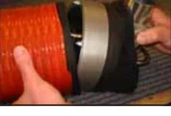
The upper adapter enters the lifting tube in the pictured construction. Check the adapter for damage and verify that the new tube seats according to the assembly instructions. A loose cover or an old tape outline is not a reliable insertion-depth gauge.
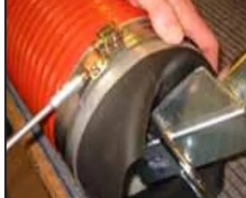
The example has two adjacent clamps at the upper joint. Inspect their specified position and straight seating before tightening to the assembly requirement. In this construction, the clamp must not sit on the tube's reinforcing spiral. Do not add more clamps or substitute a different clamp style as a guess at extra strength.
Before the sleeve is returned, the technician should inspect the complete circumference for damaged material, displaced sealing layers, sharp wire or a distorted clamp. A photograph at this stage is more useful than one taken after every connection is hidden.
Lower joint: distinguish the control head from the suction pad
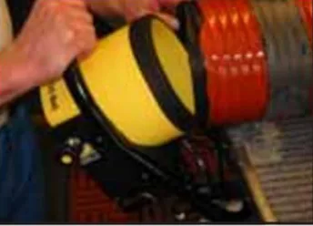
The lower tube connection joins the control-head assembly. It is not the same interface as the removable pad beneath it. Check the orientation, insertion and fastening at this joint against the correct drawing. Moving the handle or changing the pad does not correct a poorly seated tube connection.
Keep sealing surfaces clean and use the specified sealing materials. Confirm that the clamp is correctly positioned before returning the cover. Do not use the cover to pull a misaligned joint into place.
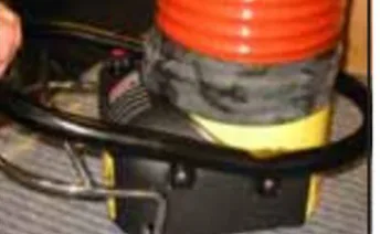
After the sleeve is returned, check that it protects the joint without fouling the controls or restricting the intended movement. The cover is the final protection, not a substitute for inspecting the hidden fastening.
Checks before returning the lifter to work
Stage | What the technician checks |
|---|---|
Before power is restored | Correct parts; secure joints; undamaged tube and covers; unobstructed controls; correct hose routing and suspension connections. |
Unloaded functional check | Movement and unloaded hover follow the machine procedure; no rubbing, unexpected drift or restriction appears through the intended range. |
Sealing and safety functions | Joint sealing and the machine's specified non-return/safety functions pass their prescribed checks. Use the model's test method and limits. |
Controlled load trial | A competent person uses the agreed test load, surface and procedure to verify pickup, movement, placement and release in an isolated test area. |
Release to service | The repair and test results are recorded; unresolved leakage, drift, damage or failed safety checks keep the equipment out of service. |
Do not invent a test weight, vacuum threshold or hold time from another model. If the machine does not hover or handle normally after repair, stop and check the installation and leakage first; do not conceal a faulty joint by changing control settings.
What to record if the replacement still does not work
Send the serial number, replacement part reference, photos of both joints before they were covered, the fault before replacement and the behaviour after replacement. State whether the problem occurs unloaded, while gripping or during movement. Include the load and surface used in the controlled test. These observations separate a joint problem from a control, filter, supply or suction-head problem.
Use the spare-part identification guide for matching components. The tube-lifter diagnostic guide provides the next checks and a fault-record form.