
When we size a vacuum tube lifter for an aquarium packing line, we start with two tanks: the heaviest one and the one with the tightest opening. The first gives us the load requirement. The second helps us choose a suction head that can reach the glass and still come out once the aquarium is sitting in its box.
Picture that last moment. The glass is resting on the packing insert. The box rim now stands between the operator and the head. On the aquarium project shown below, the agreed design paired an overhead tube lifter with two round pads. A separate drawing put four pads inside the tank. To see what each arrangement would mean on your line, we’d start with the space beside the glass.
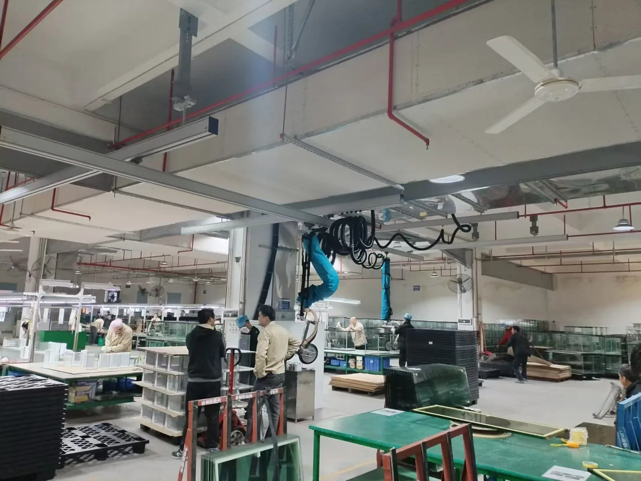
We want to see the smallest aquarium, too
The handling requirement on this job was 70 kg. The specified lifter was rated at 80 kg. If the enquiry had ended with those two numbers, we would still have had no idea how to pick up the tank. The largest aquarium was 1,200 × 400 × 800 mm and had internal partitions. The smallest was 400 × 400 × 300 mm. They shared a width on paper. From the point of view of a head trying to reach the glass, they were two quite different jobs.
In the photo below, a brace crosses the open top. Put a tape measure along the outside edge and you get the tank width. Move the tape down to the gap beside the brace and you get a dimension we can actually use to assess an internal head. We also want to see which face is available for the pads. Two tanks with the same outside dimensions can leave us with different places to grip.
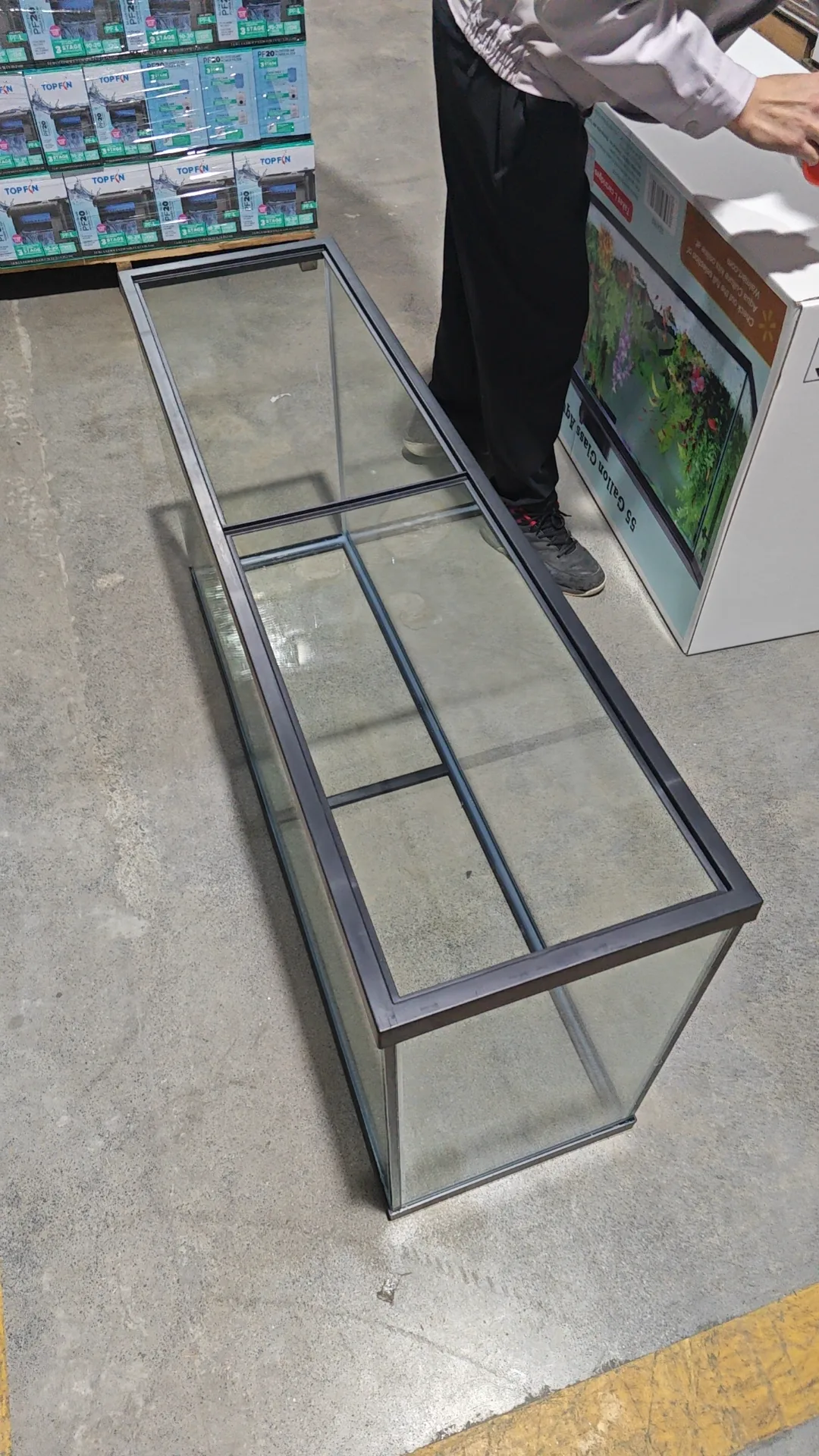
If you have a row of tank sizes, send us the heaviest one and the one with the most awkward opening. They may be different tanks. A photo of each with the intended contact face marked is a better starting point for choosing a head than a catalogue of outside dimensions.
What the two heads would change on your line
The agreed configuration for this job had two pads, each 252 mm in diameter, an extended pull handle and a rotating connection at the head. On the drawing, the assembled head is 572 mm wide and 428 mm high. When we lay this drawing beside a sketch of a workstation, the circles tell us where the pads would meet the glass. The outline around them tells us which part of the frame might meet the box first.
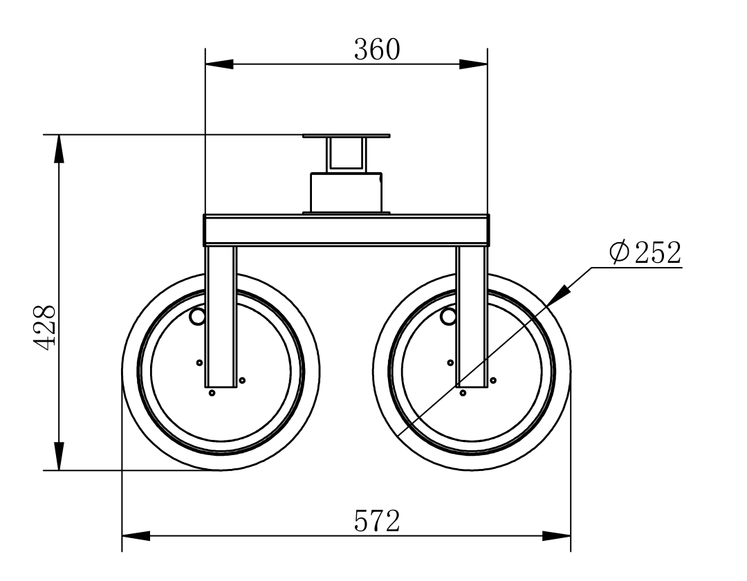
A 572 mm head beside a tank that is 400 mm wide raises a fair question. Does the whole head have to pass through that opening? That depends on which face it approaches and where the frame sits when the pads make contact. Subtracting one width from the other would give you a very precise answer to the wrong question. A side view showing the head, glass and box rim together gives us something we can make a decision on.
The other drawing from this project explores a head with four 210 mm pads working inside the tank. Follow the arms in the two side views. Their position changes, so the space the mechanism needs changes with it. On a divided tank we would want to know whether an arm has room to move beside a partition, and whether the handle can clear the rim on the way out. This was a separate design. The two-pad assembly was the one in the agreed configuration.
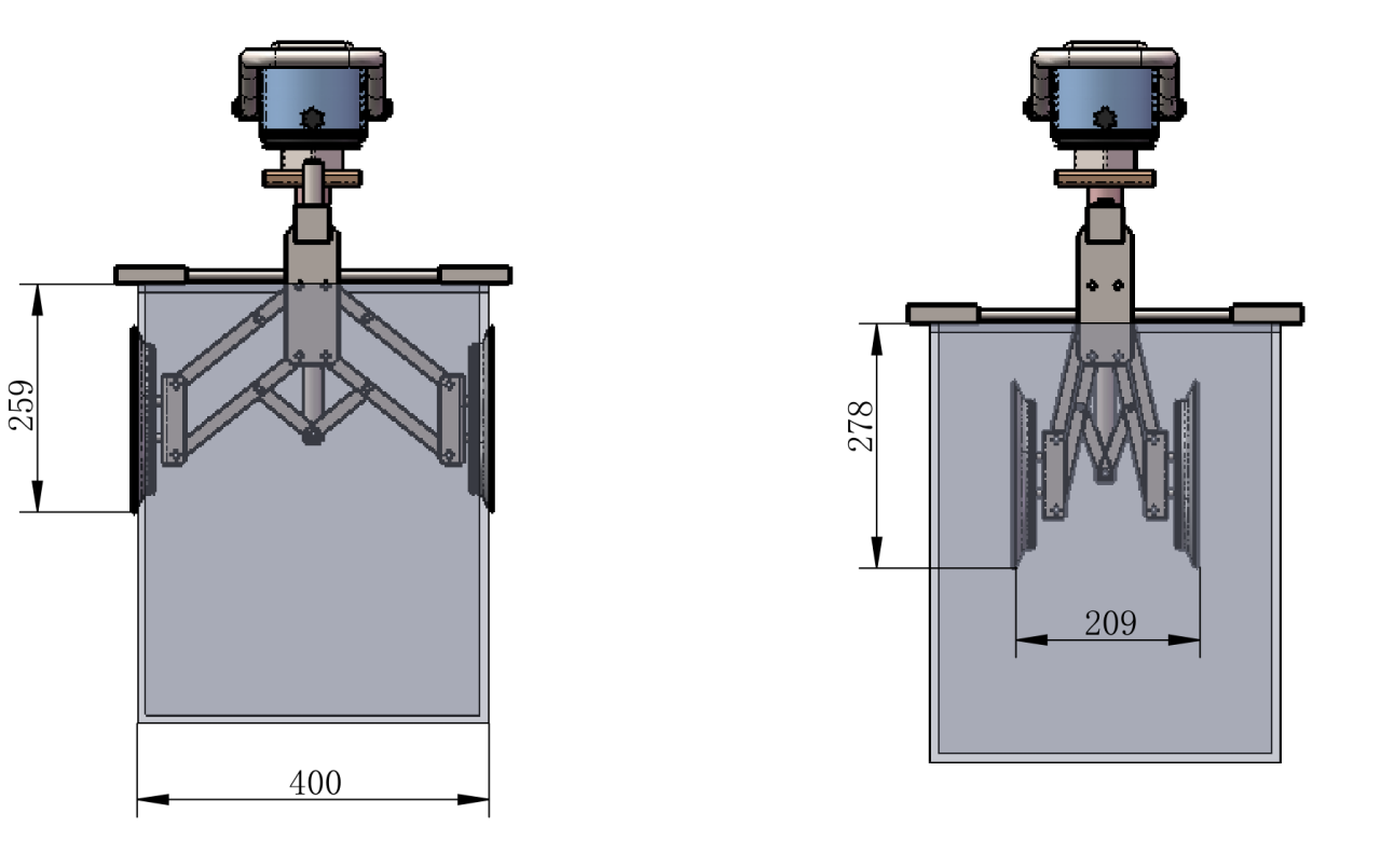
We draw the tank on the table, then draw it inside the box
The production line in this project was 700 mm high. With the tallest tank on that line, its top was already 1,500 mm above the floor. We can draw that point from two measurements you probably already have. The next useful mark on the drawing is the top edge of the packing box, with the packing inserts fitted. It may be the first obstruction the empty head meets as it comes away from the glass.
We would ask for two views of that box. From above, we can see the clear opening, including any corner protectors. From the operator’s side, we can see how far the glass will sit below the rim and where a hand can reach the handle. If the inserts go in only after the lifting head comes out, tell us. The same box, packed in a different order, presents a different opening.
The agreed rail area was 5 × 5 m. The layout also specified 2,950 mm under the beam and a head elevation range of 0–1,700 mm. These measurements refer to different parts of the installation. When we review a proposed pallet position, we place the tank, head and hanging hose at that position on the layout. A pallet can sit under the rails while its box rim still gets in the way. Buying a longer rail would solve the wrong problem in that situation.
What we would check together before dispatch
Suppose you have received a photo of the assembled lifter and both head drawings are still in your email. Count the pads in the photo. Find the matching assembly drawing and its revision. Then put the side view of your packing station next to it. We want the person accepting the equipment to be able to point to the contact face, the position where the tank comes to rest and the route the empty head takes back out. A photo with the tank suspended in open space answers only the first of those questions.
If your actual tank and packing insert are available at the factory, we can agree with you in advance which views and checks you want recorded during acceptance. If the packing station exists only at your plant, the handover should identify which clearances still need to be checked there and who will check them. Keep the completed inspection record with the drawing for the supplied assembly. That gives the receiving team something more useful than a folder containing every option discussed during the order.
What to send us for a quotation
You can start with a phone photo of the pickup table and another of the box as the operator sees it. Tell us what the heaviest tank weighs and which tank is hardest to pack. If there is a divider or a tight corner, mark it on the photo. We can use those details to discuss the contact face, the type of head and the route between stations. You don’t need to choose a pad diameter or draw a rail system before you get in touch.
Explore our vacuum tube lifters · See the aquarium packing station and rail layout