
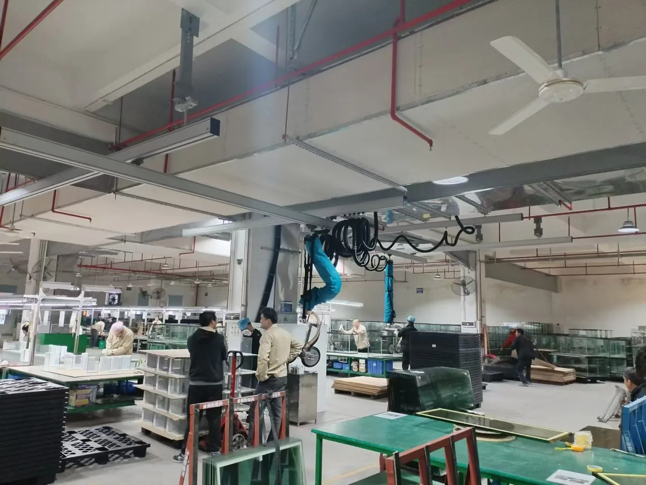
The task was packing a complete tank
This was a factory workstation for assembled aquariums, not a glass-sheet installation job. The requirements prioritized packing and then pallet transfer. Internal partitions, access from above and the position of the tank on the line mattered alongside mass.
The requirements attachment states a 70 kg workpiece. The equipment configuration states an 80 kg tube lifter. The two figures are compatible descriptions of different subjects; neither should replace the other. The complete arrangement and the tank contact still have to suit the specific workpiece.
Contact access comes before a nominal capacity comparison
The largest stated tank was 1,200 × 400 × 800 mm, including internal partitions. A smaller 400 × 400 × 300 mm size was also included for assessment where pallet handling was feasible. Those dimensions do not guarantee that the same contact position is reachable in every internal layout.
The specified head used two 252 mm pads, a rotating arrangement and an extended pull handle. Before applying a similar design, check the clear path for the head, the available glass contact areas, partitions and the operator’s reach. A plan view of the outer tank dimensions alone misses these restrictions.
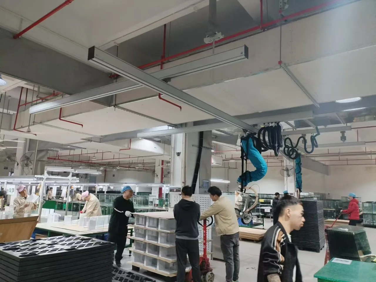
Build a height budget from the workpiece
The line height was stated as 700 mm and the largest tank height as 800 mm. Their sum is 1,500 mm: a geometric reference for the highest stated tank on that line, not a measured gripper travel result. The requirements also stated a maximum pallet-stacking height of 1,200 mm.
The selected layout specified 2,950 mm below the beam and a pad-height range of 0–1,700 mm. These dimensions must be read together with suspension and head geometry. For another site, draw the head and the complete tank at pickup, packing and placement, then check the clearance between those positions.
Why a rail workspace was used
The specified rail layout covered 5 × 5 m. The supplied photographs show overhead travel and the suspended lifting arrangement above the work area. This supported a workstation layout in which the tank could be addressed at different positions rather than treating the task as a single vertical lift.
A 5 × 5 m rail footprint is not a promise that every point is usable by the loaded head. Stops, suspension positions, tube movement, tank size and surrounding equipment reduce practical access. Discussion of a future second lifting position does not establish that two 80 kg loads may be handled simultaneously.
Verify the packing sequence, not only the lift
Review where the operator stands, how the tank is oriented for packing and whether packaging can be applied without putting hands beneath a suspended tank. Define stable supported positions for packing and for removing the head. The documented priority was packing first, then palletizing.
Use representative tanks with their actual partitions and construction. Record contact locations and any surface marks or packaging interference. Compare the largest and smallest relevant tanks separately, and include the final approach to the pallet. These are acceptance questions for a new installation, not results asserted for this record.
What another factory should provide
Provide actual tank mass and dimensions, an internal-layout drawing, photographs of accessible contact surfaces, line and pallet heights, the desired work sequence and an overhead layout. The support structure must be assessed for the proposed installation; a photograph of this factory does not approve another roof.
This case uses the agreed equipment configuration, application attachment and genuine site photographs. It describes an installed handling approach without inventing production savings, damage statistics or a model equivalence to a current catalog item. Review the tube-lifter and workstation-crane families as starting points, then specify the tank and site together.