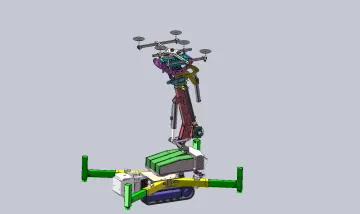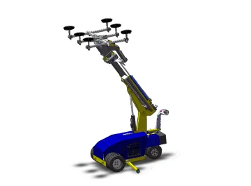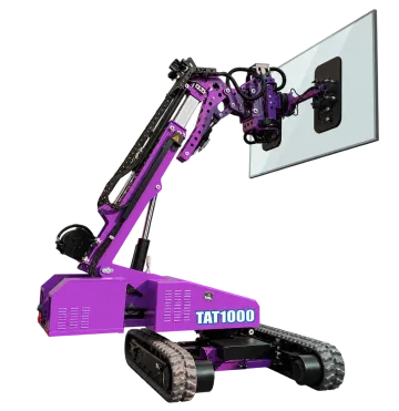
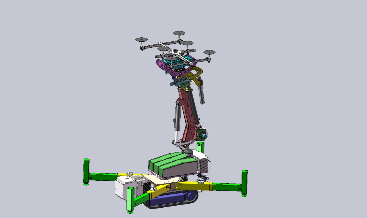
Tracked-machine envelope and setup
Read payload, attachment load, equipment weight and counterweight as separate quantities. The working load chart and installed attachment determine the permitted operating position; maximum reach and maximum capacity are not one simultaneous capability.
Compare the published configuration
Selection point | ||
|---|---|---|
Rated load (kg) | 800KG | 1500KG |
Equipment weight excluding counterweights | Approximately 2500 kg | — |
Crawler maximum loading(arm back) | — | 1500KG |
Crawler maximum loading(full extended) | — | 400KG |
Rated suction force | — | 800kg |
Equipment and intended application
The mobile chassis carries the lifting arm and vacuum head. Travel positions the machine; arm movement provides reach and height; the head aligns the glass using the listed tilt, rotation and fine-positioning functions. Each movement has its own limit, and the load envelope changes with reach and posture.
Reading the different load entries
The specification lists an 800 kg rated load, an 800 kg pad-frame capacity and a separate 600 kg end-load entry. These entries do not establish 800 kg capacity at every boom position. Use the applicable working envelope and installed head configuration for the planned movement. Equipment mass is approximately 2500 kg excluding the separate 500 kg counterweight.
Workpiece suitability and limits
Topic | Details |
|---|---|
Access to the work area | Compare the transport envelope with doors, lifts, corridors and turning spaces. Check machine mass plus the transported load against the floor and access route; width alone does not establish access. |
Placement geometry | Specify glass weight and size, final installation height, horizontal setback and any overhead obstruction. Maximum height and maximum load are separate values and must not be combined as a single operating point. |
Ground and weather | Check surface strength, slope, obstacles and the support arrangement. Gradeability is a travel specification, not permission to lift on that slope. Outdoor work also requires suitable glass, weather and site conditions. |
Configuration and supply boundaries
Topic | Details |
|---|---|
Chassis and battery | The model table defines the travel drive, battery and minimum dimensions where stated. Listed operating time is duty-dependent and is not a guarantee for every lift cycle. |
Vacuum head | Pad arrangement and vacuum circuits apply to the stated head. A fork or winch option uses a different load path and requires its own attachment instructions. |
Positioning controls | Side shift translates the head; side turning swivels it; rotation turns the pane in its plane. These functions must not be conflated when checking access around an opening. |
Counterweights and supports | Use the specified counterweight and support arrangement. Removing weights to reduce transport mass changes the working configuration; it does not preserve the same lifting envelope. |
Installation and commissioning
- Survey access and placement before delivery: door and lift dimensions, floor loading, turns, unloading space and the installation setback.
- Prepare a suitable charging point using the supplied charger input. Check battery condition and the planned duty cycle before a shift.
- Inspect the fitted pads, vacuum hoses, hydraulic lines, tyres or tracks, counterweights, support devices and emergency stop. Check both circuits when a dual system is fitted.
- Commission controls and travel without a load, then carry out the prescribed checks for the selected glass and working posture. The operator needs the machine-specific operating instructions and load envelope.
Handling sequence
- Prepare the work area and set the machine to its approved lifting configuration. Keep the pickup and destination accessible for a safe set-down.
- Position the head on intact glass contact areas, apply vacuum and check the circuit indications before taking the glass weight.
- Use the load diagram for the selected reach and height. Make controlled travel and positioning movements; use fine adjustment to align the glass without forcing it against the opening.
- Transfer the pane onto its supports and secure it by the installation procedure before releasing the vacuum. Return the machine to its transport posture before relocating it.
Inspection, maintenance and replacement parts
Topic | Details |
|---|---|
Before use | Inspect pads, hoses, vacuum indications, controls, tyres/tracks and the support arrangement. Investigate any alarm or change in movement. |
Hydraulic system | Check for leaks and damaged hoses without touching pressurised leaks. Support moving parts and isolate energy before maintenance. |
Battery and charging | Keep terminals and charging leads in serviceable condition and follow the fitted battery/charger instructions. Report declining runtime instead of assuming the catalog duration still applies. |
Service identification | Record the model and serial number, attachment type, battery specification and affected component. Pad, hydraulic-seal and controller replacements must match the actual installed version. |
Troubleshooting priorities
Topic | Details |
|---|---|
Arm movement is inhibited | Check overload indication, emergency stop, power and the permitted posture. Do not bypass an interlock to reach the target position. |
One vacuum circuit warns | Set the pane down using the prescribed safe procedure and find the cause. A second circuit does not authorise normal operation with a known fault. |
Travel or positioning becomes irregular | Stop in a supported state and inspect the route, charge level, controls and hydraulic system. Resume only after the cause is resolved. |
Frequently asked questions
How should I interpret the load figures for ET-GR-LEG-ST800?
The specification lists an 800 kg rated load, an 800 kg pad-frame capacity and a separate 600 kg end-load entry. These entries do not establish 800 kg capacity at every boom position. Use the applicable working envelope and installed head configuration for the planned movement. Equipment mass is approximately 2500 kg excluding the separate 500 kg counterweight.
Can it lift its maximum rated load to maximum height?
Only if the model load chart explicitly permits that combination. Select the curve for the actual load and check the complete reach/height path, not just the final point.
What is the difference between side shift and rotation?
Side shift moves the pane laterally without changing its angle; rotation turns it within its plane. Side turning changes the head direction relative to the arm.
Can a narrow machine automatically use a passenger lift?
No. Check the whole transport envelope, turning space, total transported mass and lift loading restrictions. The narrowest chassis width is only one of those checks.
Information for application assessment
- Identify the workpiece material, dimensions, mass, contact surface and centre of gravity. Include the least favourable item in a mixed production range.
- Describe pickup and placement positions, required orientation changes, handling frequency and the site layout.
- Identify the available power or air supply and any host machine, crane, support structure or interface that must be retained.
- State the destination market and required documentation, accessories and packing constraints so the proposed configuration can be assessed as a complete system.
Document scope
This product specification supports equipment selection and project definition. It includes the model data and application guidance presented on the product page. The operating instructions supplied for the actual machine govern commissioning, testing, maintenance procedures and safe use; this specification does not replace them.