Model configuration and selection
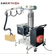
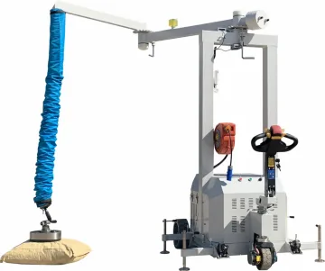
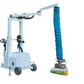
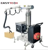
ET-TL-LEG-51 combines a height-adjustable mobile column with a 120 mm lifting tube and 1.7 m lifting stroke. The station is repositioned manually; ET-TL-LEG-59 is the battery-mobile alternative. Its rated load range is 25–40 kg, depending on the handled material and seal quality; 40 kg is not a rating for every bag or carton.
ET-TL-LEG-50 and ET-TL-LEG-51 have the same currently specified tube diameter, conditional load range, stroke and electrical connection. Neither is presented as a higher-capacity upgrade. Keep the complete model reference when specifying a replacement station or suction head. Select the suction head for packaging shape, permeability and grip position. The lifting stroke is tube travel, not the overall installed height.
Compare model configurations
Selection point | |||
|---|---|---|---|
Lifting stroke | 1.7 m | 1.7 m | 1.7 m |
Rated load range | 25–40 kg | 25–40 kg | 25–40 kg |
Load range conditions | Depends on handled material and seal quality | Depends on handled material and seal quality | Depends on handled material and seal quality |
Lifting tube diameter | 120 mm | 120 mm | 120 mm |
Station arrangement | Battery-powered repositioning with a height-adjustable column | Manual repositioning with a height-adjustable column | Manual repositioning with a height-adjustable column |
A dash means no value is specified for that comparison field; it does not mean zero or an included feature. Read each model’s complete technical data with its operating conditions.
Equipment and intended application
The same vacuum system grips the load and changes the length of the lifting tube. The operator meters air through the control handle to raise, hold or lower the workpiece. A jib or overhead rail carries the suspended tube assembly; the vacuum generator supplies airflow through a separate hose and filter.
Workpiece suitability and limits
Topic | Details |
|---|---|
Bags and sacks | Position the bag head on an intact area away from seams, folds and loose valves. Test the filled bag rather than an empty packaging sample: porosity, fill movement and the outer layer affect the grip. |
Cartons and containers | The complete pad sealing area must sit on a sound panel. Check lid strength, tape seams and any internal bag; lifting the outer carton must lift the contents without separating the packaging. |
Panels and longer workpieces | Distribute the pads across the load to control bending and overhang. Changing to a larger head adds suspended mass and requires a new assessment of tube and suspension capacity. |
Configuration and supply boundaries
Topic | Details |
|---|---|
Lifting assembly | Tube, top swivel, control unit and workpiece-matched suction head form the suspended assembly. The table specifies the model rating and tube dimensions where available. |
Handle selection | Type A is a single-hand arrangement; Type B uses a rocker control; Types C and E provide extended two-hand control. Handle reach, operator position and release access must suit both the lowest pickup and highest placement. |
Supporting system | Column jib, wall jib or overhead rail is selected for the work area. Include the vacuum generator, hose routing, filter, electrical connection and support structure in the system layout. |
Optional accessories | Quick-change heads, a vacuum-generator support bracket and an acoustic enclosure are separate configuration choices. A handle family maximum is not a new rating for the complete installed system. |
Installation and commissioning
- Map the lowest pickup, highest placement and horizontal travel. The tube length, usable lifting stroke and available ceiling height are different dimensions; allow space for the trolley, swivel, handle and workpiece.
- Provide a suitable support structure and electrical supply for the selected generator. Keep the generator inlet, cooling path and exhaust unobstructed, and route the vacuum hose without tight bends or snagging points.
- At commissioning, check generator airflow direction, hose connections and filter installation. A trained technician sets the unloaded suspension position and then checks the loaded response with the actual workpiece.
- Mobile versions require the base, support feet and arm locks to be used in the specified operating and transport positions. A forklift used to relocate a unit does not make it permissible to travel with a suspended load.
Handling sequence
- Inspect the lifting tube, supply hose, head seal, connection and support system. Establish that the selected head and packaging match the load.
- Bring the head squarely onto the contact surface and apply suction using the fitted handle. Verify an even grip before raising the load.
- Raise only enough to clear the pickup, keep control of the handle and guide the load through the planned travel path. Do not drag a load sideways with the tube.
- Lower until the destination fully supports the load, then operate the release. Keep the release control distinct from the control used to lower the load.
Inspection, maintenance and replacement parts
Topic | Details |
|---|---|
Before use | Check the head seal, tube folds, hose clamps and quick connector. Stop if the tube is cut, a connection is loose or the control response changes. |
Air path | Check the dust filter according to actual dust loading. Isolate the generator before opening the filter; do not operate without its element. Use the cleaning method specified for that element. |
Replacement selection | Identify the tube diameter and length, end connections, head seal profile and filter type. A hose of similar appearance is not automatically a lifting tube. |
After maintenance | Recheck leakage and control response unloaded, then perform the prescribed functional checks before returning to production. |
Troubleshooting priorities
Topic | Details |
|---|---|
Will not lift the intended load | Check the workpiece seal, porous packaging, blocked filter and leaking tube or hose. A higher vacuum reading alone does not prove adequate airflow for a porous bag. |
Unloaded head rises or drops unexpectedly | Stop and have the suspension adjustment and control unit checked. Do not compensate by closing an adjustment valve fully. |
Grip deteriorates during lowering | Support the load and stop use. Have the head, air path and loaded control adjustment checked before restarting. |
Frequently asked questions
What load applies to ET-TL-LEG-51?
ET-TL-LEG-51 combines a height-adjustable mobile column with a 120 mm lifting tube and 1.7 m lifting stroke. The station is repositioned manually; ET-TL-LEG-59 is the battery-mobile alternative. Its rated load range is 25–40 kg, depending on the handled material and seal quality; 40 kg is not a rating for every bag or carton.
When are separate surface load ratings used?
Porous or loose surfaces allow more leakage than sealed surfaces. If the table lists separate ratings, use the rating for the actual packaging and test a representative load. A sealed-surface figure does not apply automatically to sacks.
Does the tube length equal the lift height?
No. Tube length describes the lifting element, while stroke is its usable movement. Installation height also includes the support trolley, top swivel, control head and workpiece.
Can one system handle both bags and boxes?
It can be configured with suitable heads, but a head change also changes contact geometry and suspended weight. Each head-and-workpiece combination needs its own grip and operating check.
Information for application assessment
- Identify the workpiece material, dimensions, mass, contact surface and centre of gravity. Include the least favourable item in a mixed production range.
- Describe pickup and placement positions, required orientation changes, handling frequency and the site layout.
- Identify the available power or air supply and any host machine, crane, support structure or interface that must be retained.
- State the destination market and required documentation, accessories and packing constraints so the proposed configuration can be assessed as a complete system.
Document scope
This product specification supports equipment selection and project definition. It includes the model data and application guidance presented on the product page. The operating instructions supplied for the actual machine govern commissioning, testing, maintenance procedures and safe use; this specification does not replace them.