Model configuration and selection
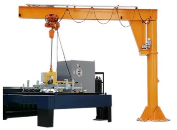
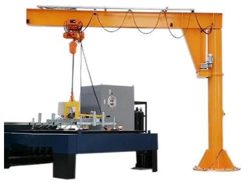
ETJSB-D1000-B4M is a motor-slewing vacuum jib system rated for 1,000 kg, with a 4,000 mm jib, motor-driven 360° slewing and 0–1,600 mm lifting stroke. It uses eight 200 mm suction pads and a 380 V operating supply.
ETJSB-D1000-B4M and ETJSB-D2000-B4M have the same values in the applicable catalogue table. The D2000 code does not establish a 2,000 kg system rating. Both are retained as complete model references with the same published capability. Motor-driven jib slewing is different from rotating or tilting the sheet at the suction frame. The 3000 × 1500 mm workpiece entry is a reference envelope subject to sheet span and stiffness, not a guarantee for every sheet of that size.
Compare model configurations
Selection point | ||
|---|---|---|
System rated load | 1000 kg | 1000 kg |
Jib length | 4000 mm | 4000 mm |
Lifting stroke | 0–1600 mm | 0–1600 mm |
Equipment dimensions | 3700 × 6000 × 2000 mm | 3700 × 6000 × 2000 mm |
Number of pads | 8 pcs | 8 pcs |
Pad diameter | 200 mm | 200 mm |
A dash means no value is specified for that comparison field; it does not mean zero or an included feature. Read each model’s complete technical data with its operating conditions.
Equipment and intended application
The crane or workstation structure supports the lifting device and its load over the intended working area. A column-and-arm structure, a complete vacuum-jib system and a cylinder/pad assembly are different supply scopes. The scope specified below determines what must be added to form a working system.
Application and integration requirements
Topic | Details |
|---|---|
Coverage | Plot the pickup and placement positions, arm sweep or rail travel and obstructions. Arm length is not the same as unobstructed usable reach. |
Headroom | Allow for the structure, trolley, hoist or cylinder, attachment and workpiece. Check the highest placement and lowest pickup against the complete installed assembly. |
Foundation or support | Assess the column foundation, wall or overhead structure for the full system loads. Do not infer an anchor size or foundation depth from rated capacity alone. |
Installation, inspection and service checks
Topic | Details |
|---|---|
Installation | Use the approved structural arrangement and foundation/anchor design. Check alignment, fixings, travel stops and routing of utilities. |
Commissioning | Test movement and controls unloaded, verify the lifting attachment and complete the prescribed load checks before production. |
Maintenance | Inspect structural connections, trolley or pivot wear, stops and the lifting assembly. Stop operation when loose fixings, distortion or abnormal travel is found. |
Troubleshooting priorities
Topic | Details |
|---|---|
Unexpected grip, motion or control behaviour | Stop with the workpiece supported. Inspect the affected connection, contact area and power or air supply, then follow the installed equipment instructions before returning to service. |
Replacement does not fit or changes performance | Check the component identity and system configuration. Do not modify interfaces or bypass protective functions to make a substitute fit. |
Frequently asked questions
What load should I use when selecting ETJSB-D1000-B4M?
The stated rated load for ETJSB-D1000-B4M is 1000 kg. Apply it only to the specified configuration and operating conditions. Include the workpiece geometry, orientation and any tooling in the application assessment; do not combine separate maximum reach, height and capacity values.
What determines compatibility?
Plot the pickup and placement positions, arm sweep or rail travel and obstructions. Arm length is not the same as unobstructed usable reach.
What needs checking beyond the listed size or load?
Allow for the structure, trolley, hoist or cylinder, attachment and workpiece. Check the highest placement and lowest pickup against the complete installed assembly.
What defines the supplied configuration?
The specified model, listed technical arrangement and accepted options define the product. Project drawings, utilities, accessories and installation interfaces must describe the same configuration.
Information for application assessment
- Identify the workpiece material, dimensions, mass, contact surface and centre of gravity. Include the least favourable item in a mixed production range.
- Describe pickup and placement positions, required orientation changes, handling frequency and the site layout.
- Identify the available power or air supply and any host machine, crane, support structure or interface that must be retained.
- State the destination market and required documentation, accessories and packing constraints so the proposed configuration can be assessed as a complete system.
Document scope
This product specification supports equipment selection and project definition. It includes the model data and application guidance presented on the product page. The operating instructions supplied for the actual machine govern commissioning, testing, maintenance procedures and safe use; this specification does not replace them.