
Start with the load’s destination
The important question is not only whether the crane can stand inside the building. The load must clear its pickup position, move without striking nearby equipment, and reach the receiving surface while the operator can still control it.
For a low workshop, begin with the highest required placement level and the lowest pickup position. Add the clearance needed above stacks or machine guards, then work upward through the vacuum frame, lifting mechanism and crane structure. Checking the roof first and the workpiece last can produce a station that fits but cannot complete the transfer.
Read the heights as different dimensions
3,220 mm: overall column height
This is the column height in the project layout. Roof beams, pipes, services and erection access still need to be considered. A single ceiling measurement at an unobstructed point does not describe the entire working area.
2,740 mm: underside of the rail
The rail sits below the top of the structure. The lifting mechanism and vacuum frame occupy part of the space beneath it, so this value is not the height to which the workpiece can be raised.
1,020 mm: pad plane in the drawn position
The drawing places the suction plane 1,020 mm above the floor in the illustrated position. That position alone does not define the upper and lower travel limits. Both end positions must be checked for the actual pickup and placement task.
The difference between column height and usable lifting height is why a shortened mast should be designed together with the lifting attachment. A lower column is not a stand-alone adjustment to make after choosing the other components.
Why the frame width matters in a low station
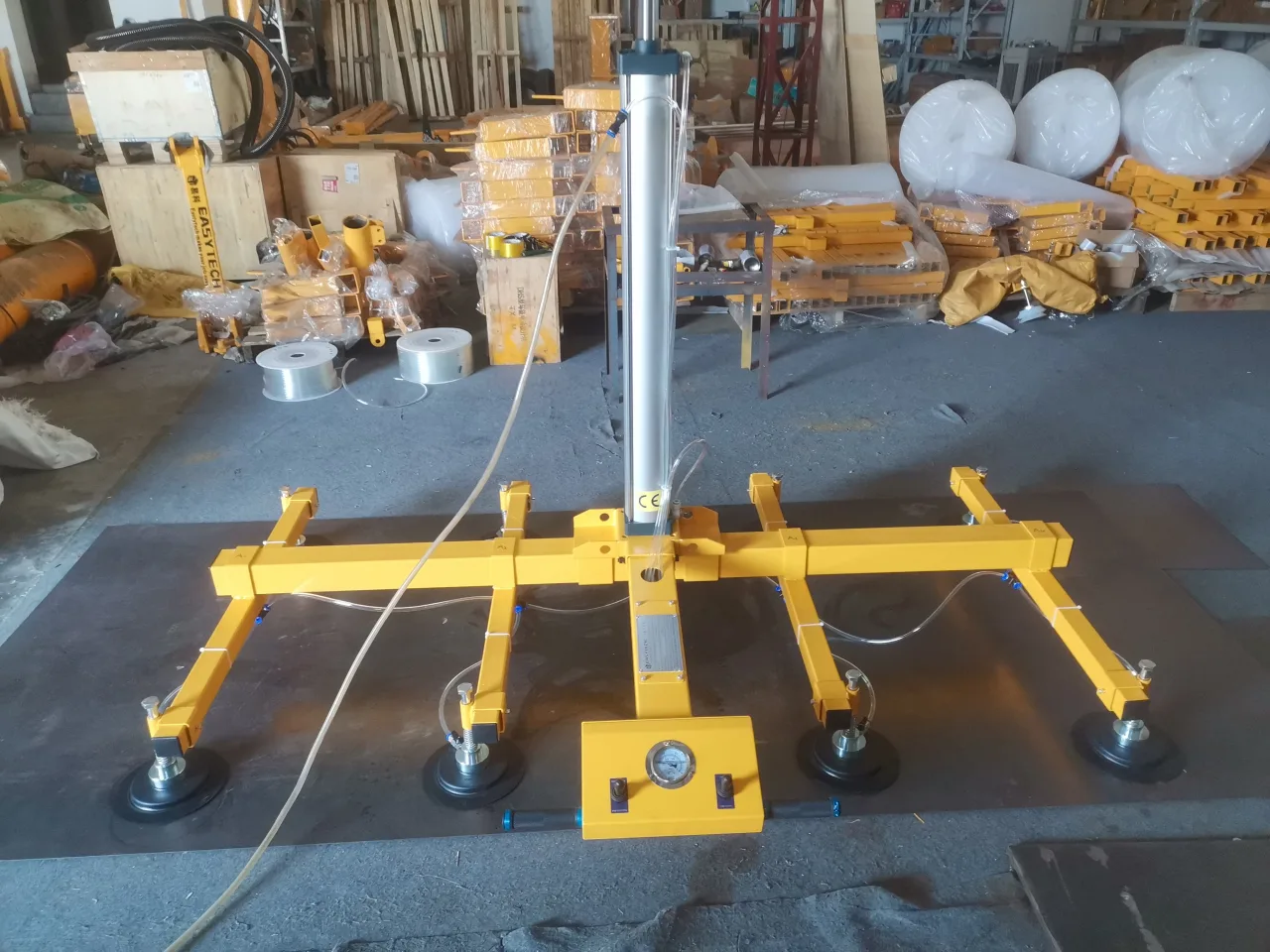
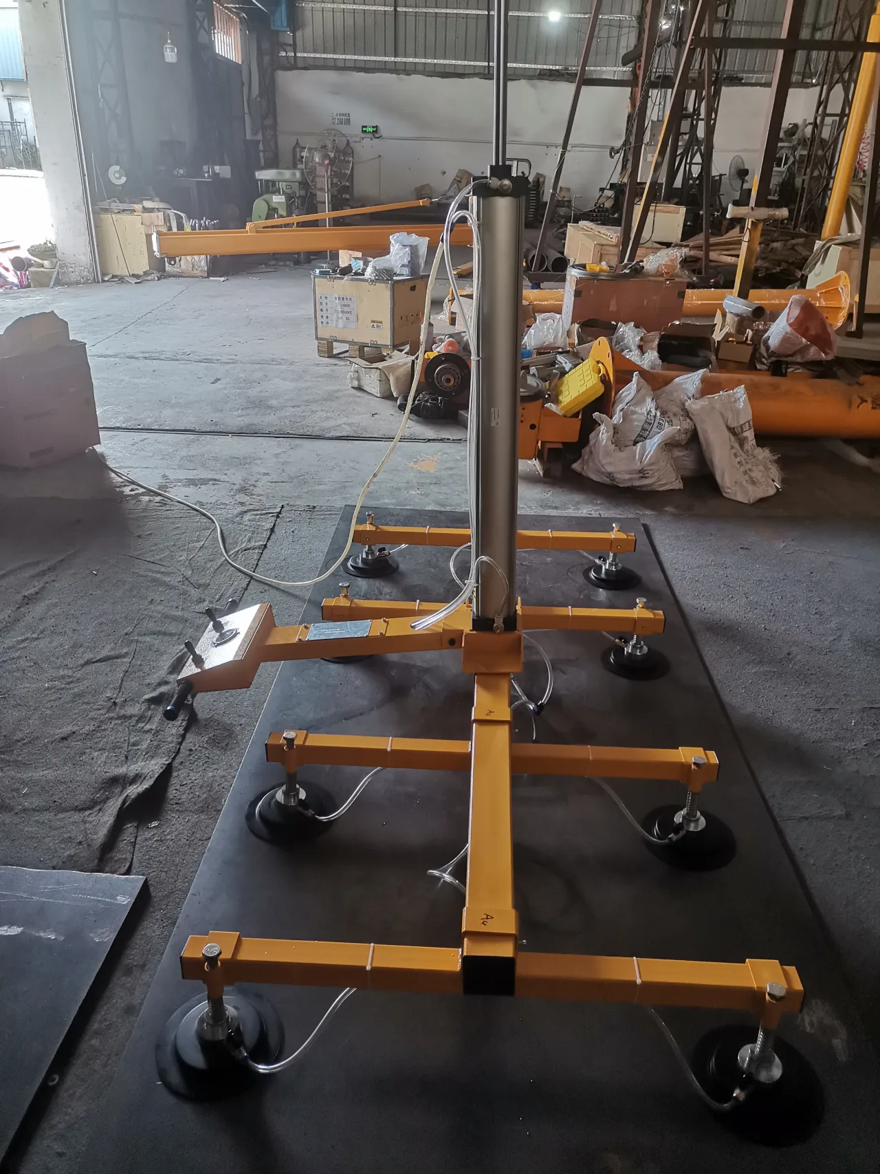
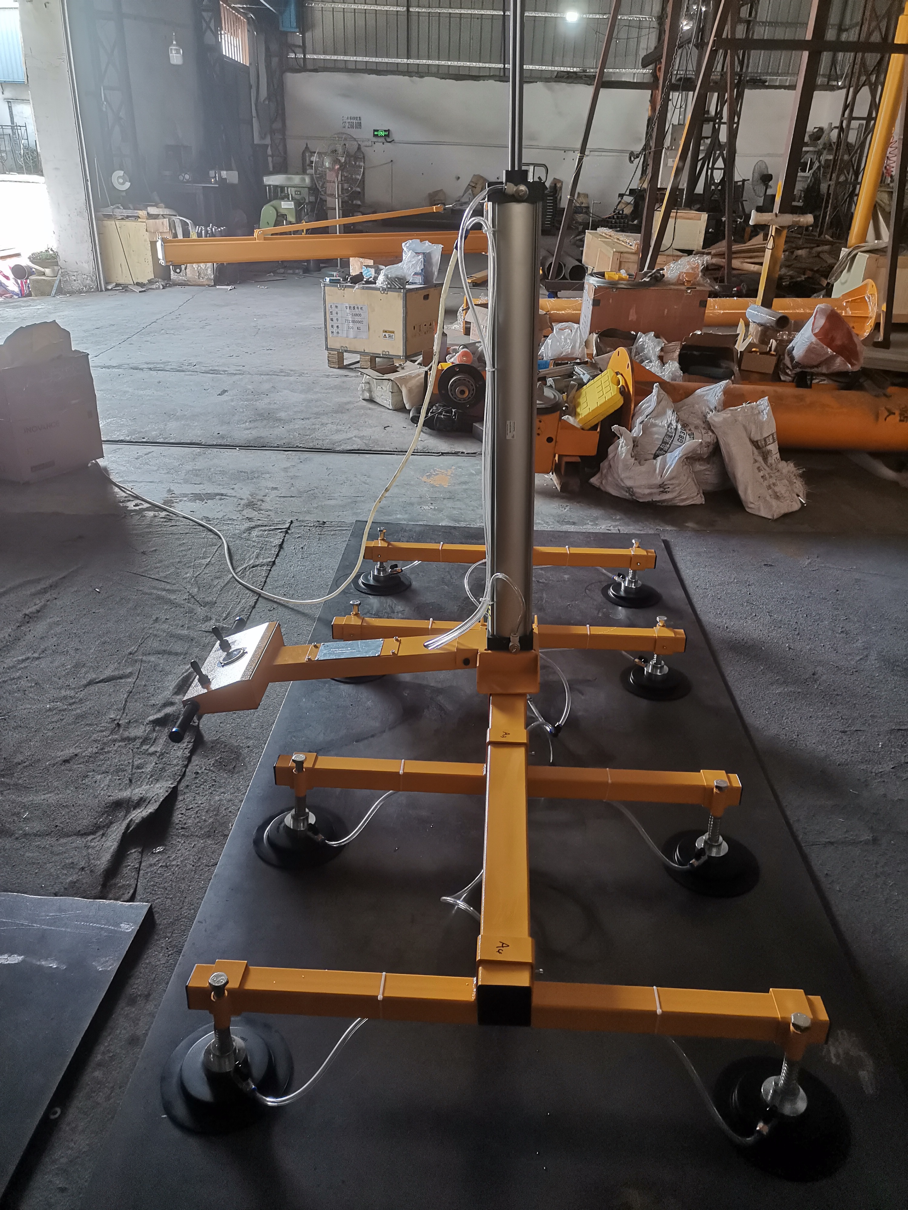
The project layout uses a 2,000 mm-wide vacuum frame. A wide frame can span the required gripping positions, but it also needs a clear path around the machine and stacks. Its outer pads must stay on suitable lifting surfaces throughout the approved configuration.
Measure the frame’s route at the height where it actually travels. A clear floor plan can hide a collision with a guard, an open machine cover or stored material higher up. Check the load’s overhang as well as the metal frame.
Put the controls in the operator’s working space
The factory photographs show the controls at the front of the frame. Their position matters at both ends of the transfer: an operator should not need to reach over the load or lean through a machine opening to use them.
Plan where the operator stands, where the air line travels and how the empty frame returns. Those details become particularly important when a compact station places the crane, workpiece and machine close together. A control that is easy to reach with the frame resting on the floor may not be easy to reach at the delivery height.
Four views that make a low-headroom enquiry useful
- A side view showing the lowest overhead obstruction and the pickup and placement levels.
- A plan view showing the column, machine, stacks and the operator’s standing positions.
- A photograph and dimensions of the largest workpiece, including its lifting face and overhang.
- Details of the floor or supporting structure for the proposed installation.
These let the crane layout, lifting attachment and work sequence be assessed as one system. The supporting floor and anchors need their own structural assessment; the dimensions of a lifting drawing do not establish that an existing floor is suitable.
Can the same height dimensions be used in another workshop?
Only as a starting point for a layout discussion. A different machine height, pickup level, workpiece or overhead obstruction can change the required geometry. Check both loaded and empty movements rather than copying a column height.
Does this case provide a maximum load or travel specification?
Use the rating and travel limits supplied for the exact delivered configuration. The project identifier and the dimensions shown here are for identifying and explaining the arrangement; they are not a replacement for its rated operating limits.