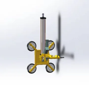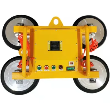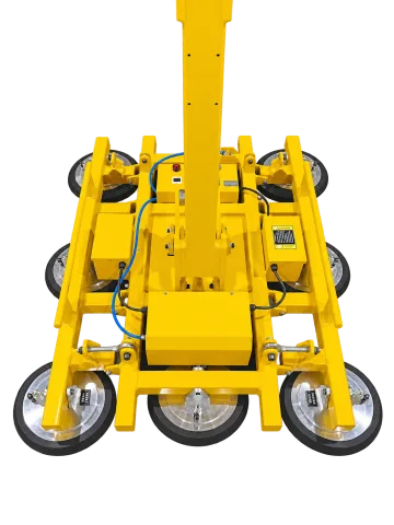
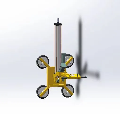
180° glass turning: pneumatic or electric actuation
The two 300 kg arrangements use six Ø300 mm pads but different tilt drives. The required utility and control arrangement therefore matter even though the nominal load is the same. Their project-specific supply scope must be identified before ordering.
Compare the published configuration
Selection point | ||
|---|---|---|
Tilting | 180°, pneumatic cylinder | 180°, electric actuator |
Battery | — | 12 V |
Rated load | 300 kg | 300 kg |
Number of pads | 6 pcs | 6 pcs |
Equipment and intended application
Vacuum seals the suction pads against the glass; the lifting frame transfers the load to the suspension point. The crane or other supporting machine provides the lift. Tilting changes the glass between horizontal and vertical, while rotation turns it within its plane. The listed drive method applies separately to each movement.
Workpiece suitability and limits
Topic | Details |
|---|---|
Contact surface | Use an intact, clean sealing area large enough for every active pad. Holes, frit, textured surfaces, films and protective coatings can change leakage or friction and need an actual-surface test. |
Glass geometry | Check panel weight, length, width, thickness, centre of gravity and unsupported overhang. The frame must support the glass without excessive bending; pad diameter alone does not determine the maximum panel size. |
Curved or asymmetric glass | Use the configuration specifically intended for the curvature and contact positions. A flat-glass load rating must not be transferred to a curved-pad option or an off-centre arrangement. |
Configuration and supply boundaries
Topic | Details |
|---|---|
Vacuum and pad arrangement | The pad count, pad size, circuit description and power supply in the table define the listed version. A dual-circuit description is not evidence of a particular certification or of unrestricted continued lifting after a fault. |
Movement and control | Manual, pneumatic, electric and hydraulic movements require different operator actions and utilities. Distinguish vacuum grip/release control from tilt and rotation control. |
Suspension and support | The lifter is a below-the-hook attachment unless a different mounting is stated. The supporting crane must carry the workpiece, lifter and all associated lifting accessories. |
Options | Only the alternatives explicitly listed for this product are specified options. Additional arms, curved pads, remote controls or a different power package require a defined configuration and corresponding load assessment. |
Installation and commissioning
- Check the crane hook, suspension connection and retention latch. Confirm the total suspended mass and clearances through the entire lift and turning path.
- Set the pad spread around the panel centre of gravity. Lock all adjustable members and route hoses so they cannot kink, rub or become trapped during tilting and rotation.
- For a battery version, check charge state, battery connections and charger input. For a mains or compressed-air version, use the stated utility requirements; a charging voltage is not an operating supply.
- Before production, perform the prescribed vacuum, warning-device and functional checks with the installed arrangement. Changing pad positions or removing pads requires a capacity and balance review.
Handling sequence
- Inspect pads, frame, suspension, hoses and available power. Check the panel and plan a supported set-down location.
- Place all active pads fully on the intended contact areas. Apply vacuum and check the indication for every fitted circuit before lifting.
- Make a controlled initial lift and check balance. Keep people clear of the load path and use only the listed tilt/rotation functions within the approved load configuration.
- Set the glass onto a suitable support, ensure the weight has transferred to it, then release vacuum. Do not use the release control while the panel is suspended.
Inspection, maintenance and replacement parts
Topic | Details |
|---|---|
Pads and seals | Keep contact faces clean using a material-compatible method. Replace damaged, hardened or worn seals; check for marks or chemical effects on coated glass. |
Vacuum circuit | Inspect hoses, connectors, filters and gauges. Check fitted warning and non-return devices according to the operating instructions; never assume an indefinite hold time after power loss. |
Moving frame | Check pad mounts, locking pins, extension arms and tilt/rotation mechanisms. Isolate power and support moving parts before repair. |
Battery and storage | Inspect the battery and charging leads, maintain charge according to the battery instructions and store the pad faces clear of damaging surfaces. |
Troubleshooting priorities
Topic | Details |
|---|---|
Vacuum does not reach the operating range | Keep the glass supported. Check sealing area, contamination, pad condition, closed valves, hose leaks and power supply before a further lift. |
Vacuum falls or a warning operates during lifting | Set the load down by the prescribed safe procedure and stop use. Find the leak or power fault; do not silence the warning and continue lifting. |
Glass tilts unexpectedly or a lock will not engage | Support the panel, stop movement and check balance, pad layout and the locking/drive mechanism. Do not force a loaded mechanism past its travel limit. |
Frequently asked questions
What load should I use when selecting ET-GL-FLIP180-P300?
The stated rated load for ET-GL-FLIP180-P300 is 300 kg. Apply it only to the specified configuration and operating conditions. Include the workpiece geometry, orientation and any tooling in the application assessment; do not combine separate maximum reach, height and capacity values.
Can I remove pads to handle smaller glass?
Only with an approved layout and revised capacity. A disconnected pad contributes no holding force; balance, glass overhang and the active circuit arrangement must also remain suitable.
Does the charger voltage power the lift?
On battery equipment the battery powers the on-board functions and the charger has its own AC input. A mains-powered variant is a different configuration, not an automatic operating mode of the battery unit.
Is a load rating sufficient to select the lifter?
No. The pad contact area, glass size and thickness, orientation, centre of gravity and supporting crane all have to fit the task. The technical table and configuration notes should be read together.
Information for application assessment
- Identify the workpiece material, dimensions, mass, contact surface and centre of gravity. Include the least favourable item in a mixed production range.
- Describe pickup and placement positions, required orientation changes, handling frequency and the site layout.
- Identify the available power or air supply and any host machine, crane, support structure or interface that must be retained.
- State the destination market and required documentation, accessories and packing constraints so the proposed configuration can be assessed as a complete system.
Document scope
This product specification supports equipment selection and project definition. It includes the model data and application guidance presented on the product page. The operating instructions supplied for the actual machine govern commissioning, testing, maintenance procedures and safe use; this specification does not replace them.