
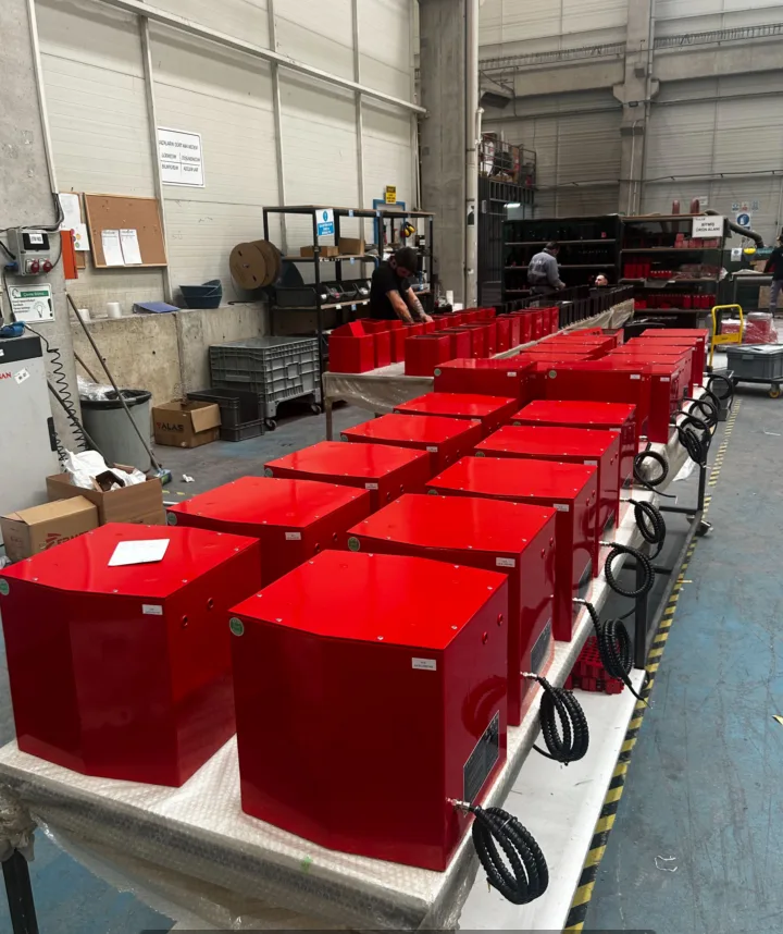
A flat patch matters more than the outside dimensions
The raised sides and folded edges in these parts make pad placement a separate design task. A pad has to fit on a continuous contact area, and the lifting assembly must leave room for the edges around it. A drawing of the outer rectangle alone cannot settle the choice.
For the proposed two-pad arrangement, each 85 × 200 mm contact footprint needs to be checked on the intended lifting face. Include nearby bends, holes, welds and coatings. If the part family changes, compare the least favourable gripping face rather than assuming that every part with a similar weight uses the same head.
The centre of gravity also matters. A formed part can hang unevenly when a flange or deeper section puts more mass on one side. Show the orientation at pickup and at placement, including whether the part needs to remain level or turn during the transfer.
Two approaches considered for the station
The project explored a pneumatic manipulator as well as a vacuum tube-lifting arrangement. Both can assist handling, but their movement, services and control feel need to suit the task.
Pneumatic manipulator option
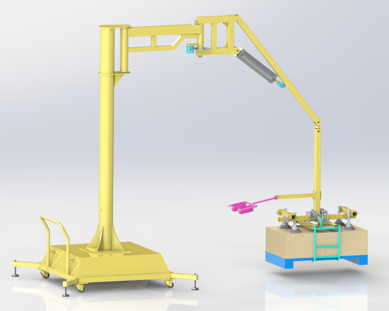
The earlier concept uses a dedicated mechanical arrangement above the gripping head. It brings the air supply, arm geometry and required movement into the selection. Available compressed-air pressure and flow, control position and the complete work envelope all need checking.
Vacuum tube-lifter proposal
The later proposal combines a lifting tube, an extended handle and a two-pad head. The tube provides vertical lifting movement while the support crane covers the transfer area. The pad geometry and leakage behaviour of the actual parts remain central to selection.
What the later tube-lifter proposal specifies
The later project configuration is a 45 kg assembly with two 85 × 200 mm pads on a 350 mm beam, a Ø120 mm lifting tube of 2,550 mm length, and a Type B extended control handle. Its proposed vacuum source is 2.2 kW at 380 V, three-phase, 50 Hz.
The extended handle is relevant where the operator needs to reach the lifting controls around the workpiece. Its usefulness depends on the actual standing position and access at both ends of the transfer. A longer handle is not automatically better if it interferes with another part of the machine.
The 45 kg value describes this custom proposal. It should not be applied to another tube-lifter model or derived from a similar model code. The finished configuration and its approved lifting conditions must match the actual workpieces.
Fixed station or movable base?
A fixed station can be arranged around a repeatable pickup and placement path. A movable base can be useful when the workstation has to change, but it introduces transport position, floor condition, stabilisation and clearance checks. It does not mean the machine can be moved while carrying a suspended part.
The earlier mobile concept includes a base and supporting structure that occupy floor space. That footprint belongs in the layout alongside the workpiece stacks and operator. The maximum arm reach alone does not describe the space needed for the station.
Match the holding pattern to the process
A quick transfer and a prolonged hold are different duties. Explain whether the part moves directly to a support, waits while another operation finishes, or needs repeated small positioning movements. This helps select the vacuum source, controls and operating duty without assuming that every pump or blower behaves the same way.
Include the receiving support in the discussion. If the process needs a part held in mid-air for assembly, that requirement should be designed explicitly; it should not emerge as an improvised use of a transfer lifter.
Make the next design decision with three pieces of information
- Part geometry: a drawing and photographs of the actual gripping face, plus the mass and centre-of-gravity information available for the limiting variants.
- Movement: pickup orientation, required travel, placement orientation and any need to tilt or hold the part.
- Station: working heights, available air and electrical supply, obstacles, and whether relocation is genuinely required.
Can a vacuum lifter handle perforated or heavily contoured parts?
Only if the gripping system is suitable for the actual surface and leakage. A pad crossing a hole or bend cannot be assessed from the part’s mass alone. If a reliable contact arrangement is unavailable, a mechanical gripper may be more appropriate.
How is the final configuration selected?
The final machine is specified after checking the actual parts and station: pad contact, part balance, pickup and placement positions, and the available operating space.