
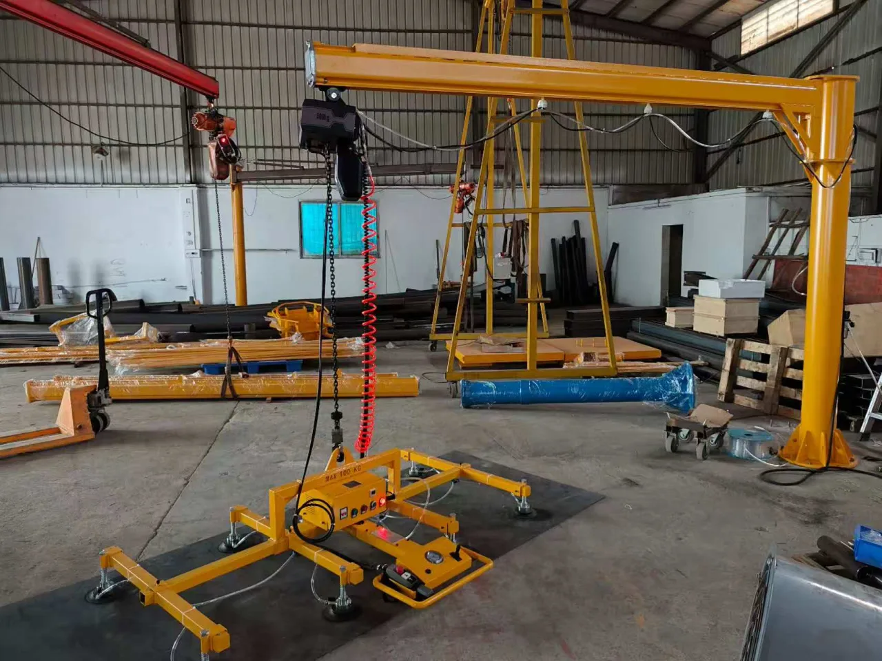
Choose the gripping face before choosing the pad
A panel’s total width says little about how much flat surface is available for suction. Edges, profiles, recesses and hardware can leave only narrow contact zones. A broad pad that overlaps a groove may be less useful than a smaller pad that fits fully on the intended surface.
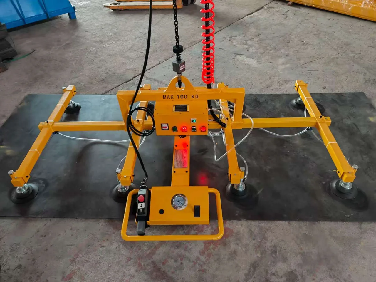
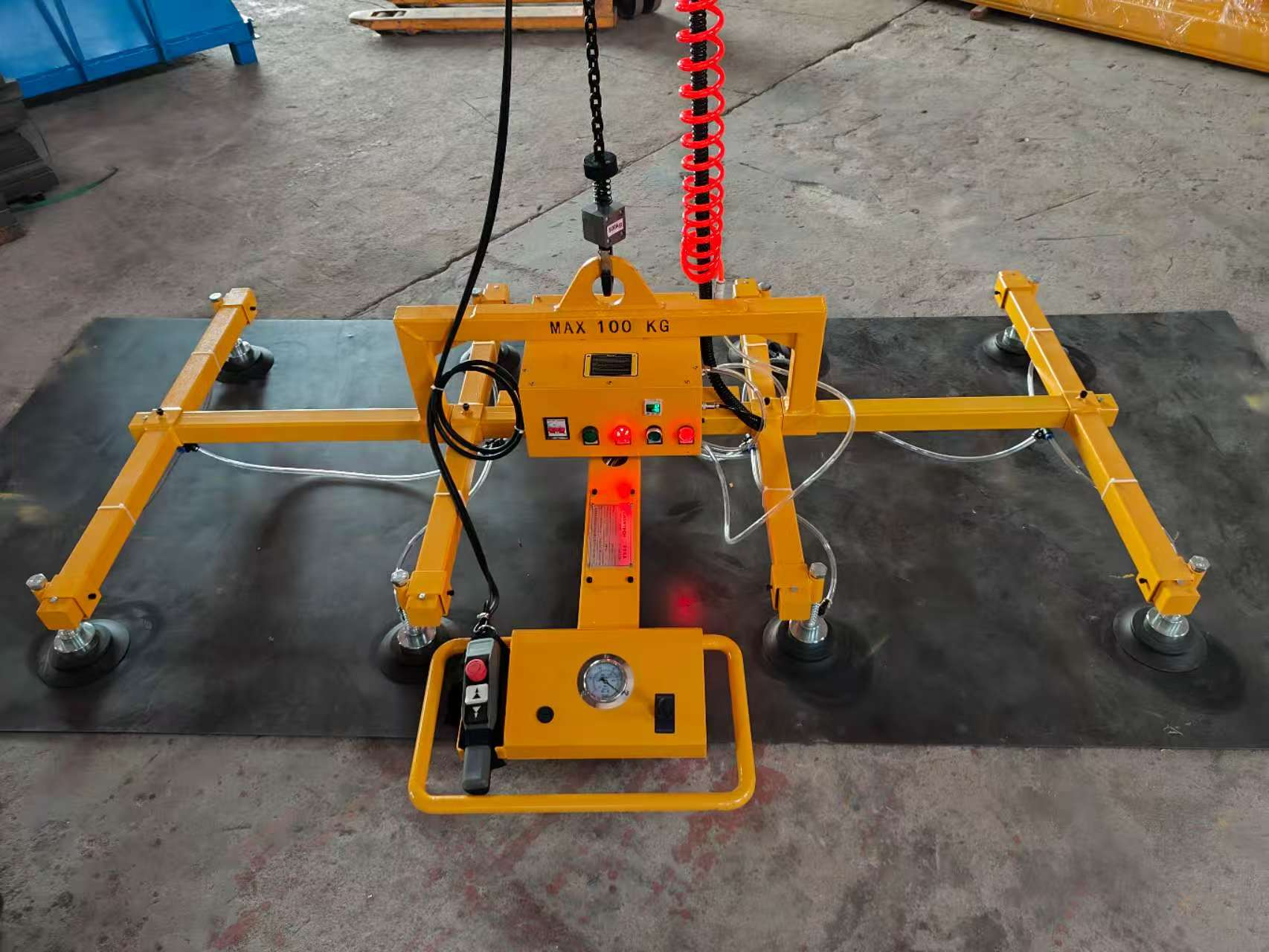
The project included round and oval pad tooling. The photographs show the two shapes and their fittings. The purpose of the choice is to match the available contact area; it does not make either shape suitable for every door material or finish.
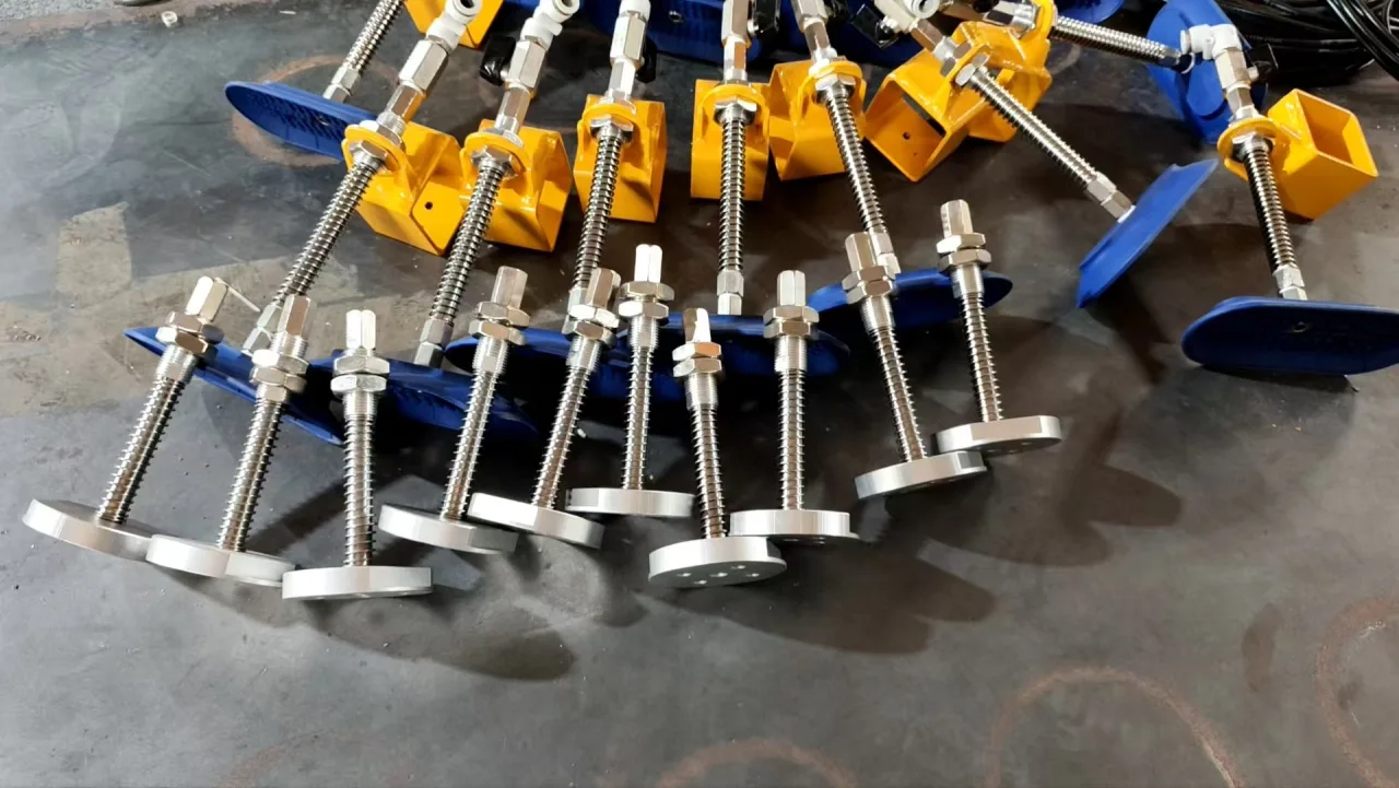
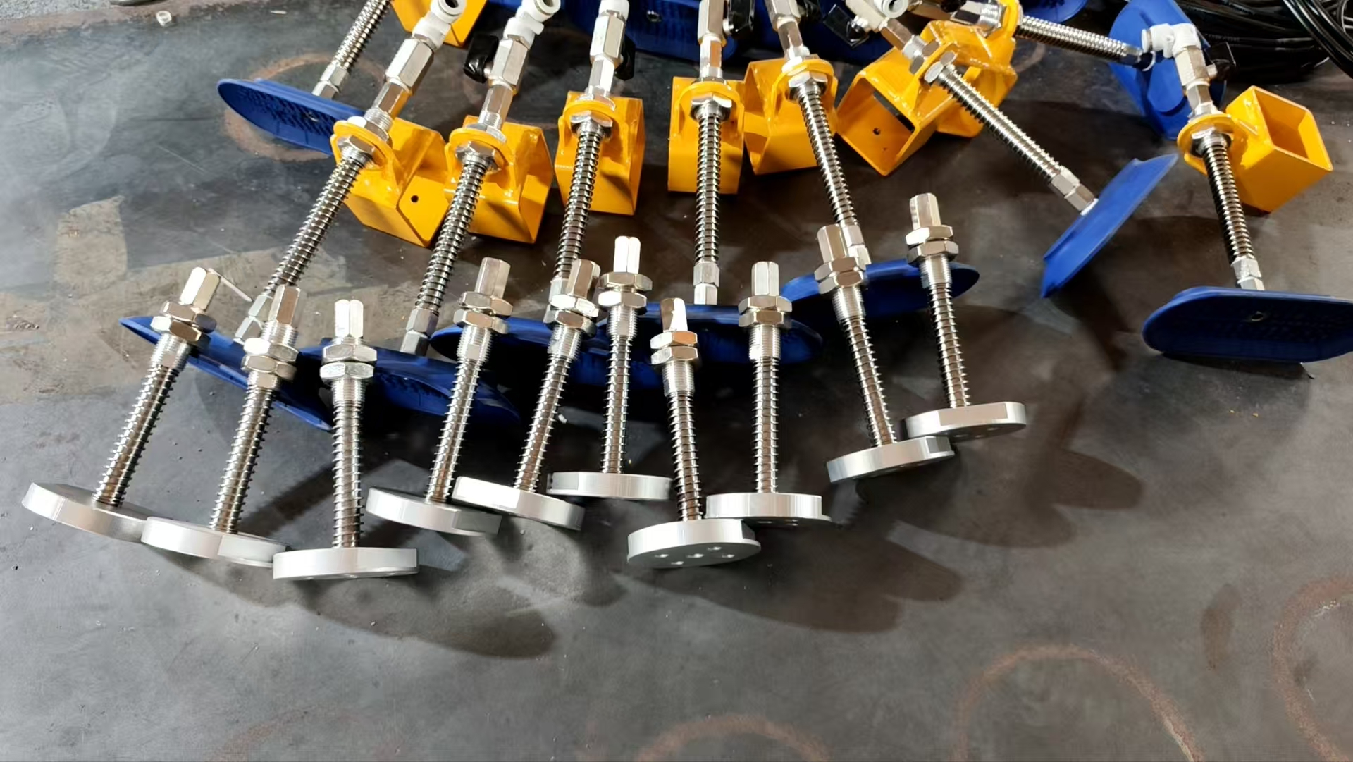
For selection, mark the permitted gripping zones on a panel drawing and identify the finish at those points. Include the smallest panel as well as the largest. If adhesive, protective film or surface texture will be present during lifting, assess that actual condition rather than a clean sample of the base material.
A 2,600 mm layout is not a 2,600 mm lift
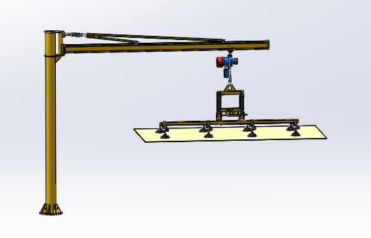
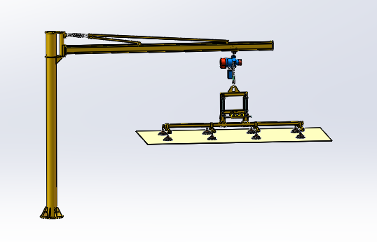
The dimensional proposal for this project illustrates the space taken by the structure, hoist and lifting attachment. Its calculation uses a 2,600 mm overall height, less 250 mm of structure, 530 mm of hoist envelope and 550 mm of lifting attachment:
2,600 − 250 − 530 − 550 = 1,270 mm
Proposed height at the lifting face in this layout.
This is a layout calculation, not a measured final travel specification. It explains why a crane can fit in a building while the suction frame still cannot clear a high stack. The actual machine bed, panel thickness, pickup height and required separation must be checked against the delivered geometry.
Do not combine component ratings into a larger capacity
The vacuum frame carries a maximum 100 kg marking. That remains a limit for the frame even if the chain hoist has a higher rating. The hoist must also carry the attachment’s own weight, and the crane, suspension and gripping arrangement each have limits of their own.
Round and oval pad sets are configuration choices, not interchangeable capacity labels. Use the approved pad arrangement and operating limits for the panel being handled; do not assume that swapping a pad preserves the capacity for a different surface.
Plan the hand-off at the machine, not just the pickup
Approach
Check the panel and frame against guards, covers and the machine opening. Include the clearance needed to position the panel above the receiving supports without trapping the operator between the load and machine.
Placement
The operator needs to see the receiving position and reach the controls. Establish a clear support position before release, so that the panel is carried by the machine bed rather than by a partially released lifting attachment.
Return
After release, the pads and frame need a clear route out of the machine. Check the return path with covers and guards in their normal positions, not only with the machine opened for installation.
Where loading interacts with machine movement, the station’s guarding and operating sequence need to be coordinated with the machine. A vacuum lifting attachment alone does not provide an automated machine-loading interlock.
What to send for a comparable station
A short panel list is more useful than a single maximum weight. Include dimensions, mass, finish and allowed gripping zones for the limiting panel variants. Add the gluing-machine bed height, loading opening, nearby obstacles, lowest overhead obstruction and preferred operator position.
Also identify the available electrical and air supplies and the proposed crane mounting location. Floor thickness by itself does not establish an acceptable crane foundation; slab condition, reinforcement, loads and anchoring need a suitable structural assessment.
Can it lift a porous panel?
That depends on the surface, leakage and the matched vacuum system. These photos are not a blanket approval for unfinished MDF, textured skins or every coated door. Provide the actual lifting-face material or a representative sample.
Can the panel be tilted for another process?
A different movement must be included in the specification. This case explains loading geometry and pad access; it should not be used to assume an additional tilting capability.