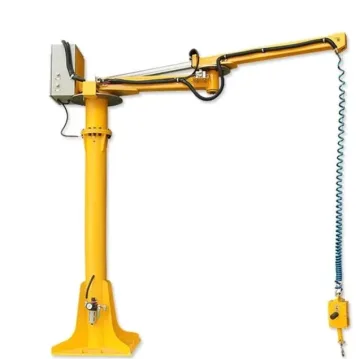
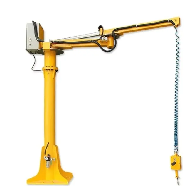
Cable-balancer working area
These column-mounted pneumatic configurations share a 500–2,500 mm working radius and 1,500 mm vertical stroke, with different loads and machine weights. The selected end tool still determines how the workpiece is gripped and oriented.
Compare the published configuration
Selection point | |||
|---|---|---|---|
Load | 100 kg | 200 kg | 300 kg |
Machine weight | 270 kg | 300 kg | 350 kg |
Vertical stroke | 1500 mm | 1500 mm | 1500 mm |
Minimum working radius | 500 mm | 500 mm | 500 mm |
Maximum working radius | 2500 mm | 2500 mm | 2500 mm |
Equipment and intended application
A balancing mechanism supports the end effector and workpiece while the operator guides their position. The gripper supplies the workpiece-specific connection; the arm or cable mechanism and mounting structure define the working envelope. The end-effector mass is part of the load that the system must support.
Workpiece suitability and limits
Topic | Details |
|---|---|
Workpiece and grip | Identify the lifting feature, surface condition, centre of gravity and required orientation. A clamp, hook and vacuum head solve different grip problems and are not interchangeable load ratings. |
Machine access | Check both the minimum and maximum working radius, the lowest and highest end positions and the space occupied by the arm above them. |
Assembly work | Describe whether the operator needs to hold a part level, turn it, reach into a machine or maintain a floating load while aligning fasteners. |
Configuration and supply boundaries
Topic | Details |
|---|---|
Balancer | The balancing unit carries the combined end-effector and workpiece load within its stated envelope. |
End effector | The fixture is designed around the actual workpiece and handling sequence. Its weight, gripping points and orientation functions are part of the configuration. |
Mounting | Fixed, mobile, overhead and rail-mounted arrangements have different structural and clearance requirements. Use the mounting stated for the selected model. |
Utilities | Pneumatic and electric drive versions are separate configurations. Apply only the pressure or electrical requirements actually listed for the model. |
Installation and commissioning
- Plot pickup and placement coordinates relative to the mounting point. Include the minimum-radius blind area and the full moving-arm envelope.
- Design the foundation, overhead support or mobile base for the specified system and operating loads. A matching bolt pattern alone does not verify structural capacity.
- Install the selected fixture and utility supply, then commission its balance, grip/release controls and locking functions with representative workpieces.
- Provide the operator with a clear path and access to the controls at every required posture. Reassess the system when the fixture or workpiece changes.
Handling sequence
- Inspect mounting, joints, fixture and the applicable utility supply.
- Engage the fixture using its defined gripping procedure and verify that the workpiece is secure.
- Guide the balanced load through the clear working envelope without forcing it against a travel stop.
- Support the workpiece at the destination before releasing the fixture; park the arm in its designated position.
Inspection, maintenance and replacement parts
Topic | Details |
|---|---|
Arm and mounting | Inspect fixings, joints and locking functions for looseness, wear or drift. |
Fixture | Check contact pads, clamp jaws, hooks or vacuum elements according to the installed gripping method. |
Pneumatic versions | Check air quality, filter bowl, hoses and leakage; do not alter factory balance settings to compensate for a fault. |
Changed loads | Recheck balance and grip after replacing an end effector or changing the workpiece mass or centre of gravity. |
Troubleshooting priorities
Topic | Details |
|---|---|
Load drifts or balance changes | Support the workpiece and check the fixture mass, utility supply and balance system before continuing. |
Cannot reach the placement | Check minimum radius, maximum radius, end height and obstacles. Do not force the arm beyond its mechanical envelope. |
Fixture slips | Stop use and review gripping surface, fixture engagement and the actual workpiece geometry. |
Frequently asked questions
What load should I use when selecting SAC-RS100?
The stated rated load for SAC-RS100 is 100 kg. Apply it only to the specified configuration and operating conditions. Include the workpiece geometry, orientation and any tooling in the application assessment; do not combine separate maximum reach, height and capacity values.
Does the load figure include the gripper?
The balancing mechanism supports the end effector as well as the workpiece. Assess their combined mass and the centre of gravity when sizing the system.
Why does minimum radius matter?
A position too close to the column may be unreachable even though it is inside the maximum-radius circle. Plot both pickup and placement against the complete arm envelope.
Can one fixture handle every part?
Only if its grip, adjustment and load limits cover those parts. Part families with different centres of gravity or gripping features may need different fixtures.
Information for application assessment
- Identify the workpiece material, dimensions, mass, contact surface and centre of gravity. Include the least favourable item in a mixed production range.
- Describe pickup and placement positions, required orientation changes, handling frequency and the site layout.
- Identify the available power or air supply and any host machine, crane, support structure or interface that must be retained.
- State the destination market and required documentation, accessories and packing constraints so the proposed configuration can be assessed as a complete system.
Document scope
This product specification supports equipment selection and project definition. It includes the model data and application guidance presented on the product page. The operating instructions supplied for the actual machine govern commissioning, testing, maintenance procedures and safe use; this specification does not replace them.