
The ceiling was the deciding constraint
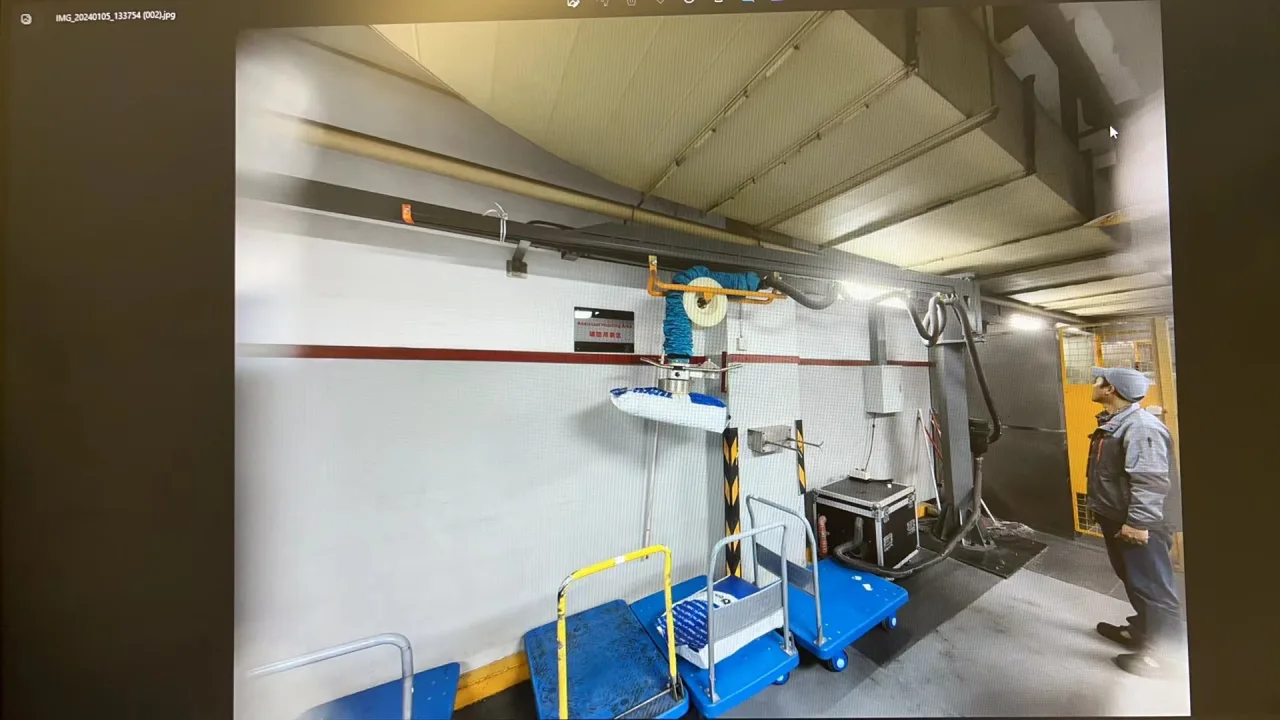
The task was to take sealed bags of plastic pellets from a pallet and bring them to a hopper. The requirements specified bags weighing no more than 30 kg, three feeding positions along a 7,500 mm area and roughly 2,500 mm between pallet and hopper at each position. The effective building height was only 2,600 mm.
A conventional hanging arrangement has to accommodate the support, suspension, lifting tube, control head and bag within the same vertical envelope. The project proposal stated that its standard arrangement required about 2,750 mm. That figure describes the proposed configuration, not a minimum height for every vacuum tube lifter. Selecting a higher nominal load capacity would not have solved this geometric problem.
What folding the tube changed
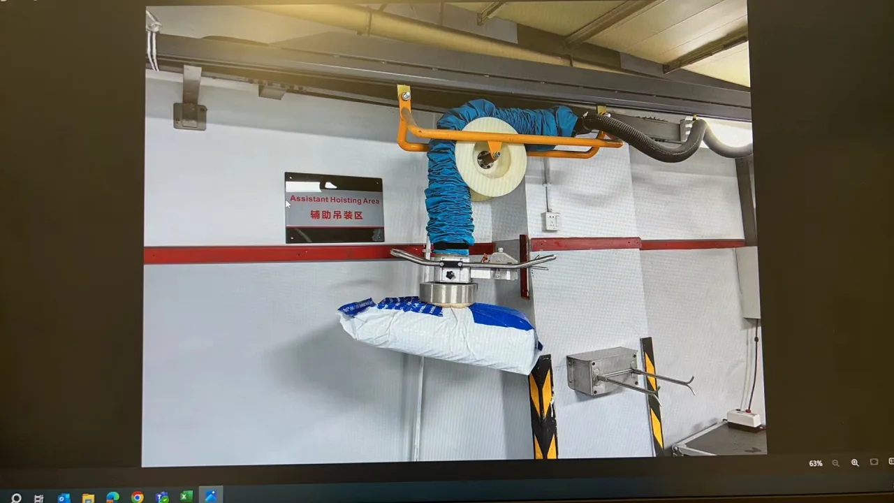
The selected layout redirected part of the tube above the working head, leaving more of the available height for the bag movement. The proposal placed the suspension at approximately 2,200 mm. The installation photographs show the overhead tube path and the compact head beneath it.
This solution used horizontal space. The proposed 4,200 mm arm did not provide a full 4,200 mm working radius after the fold: about 800 mm was occupied by the folded arrangement, leaving approximately 3,400 mm of effective reach in the proposal. A reach check must use the working head position, not just the beam length.
Read the target and the illustration separately
The requested pickup-to-placement envelope was 300–1,700 mm. A separate illustration in the proposal compared a conventional arrangement at about 900 mm with the folded arrangement at about 1,600 mm. Those values are design illustrations, not an instrumented test of the finished installation.
For a similar project, require the final arrangement drawing to show the actual pickup surface, the hopper opening, the bag height and the head at both ends of its stroke. An illustration that almost reaches a target is not a substitute for checking the full transfer path.
Check the entire work sequence
Start with the lowest bag remaining on the pallet. Confirm that the head can approach the bag without the handle or tube colliding with adjacent equipment. Then trace the lift and horizontal transfer, including the space occupied by the filled bag. At the hopper, verify both clearance and an accessible operating position.
Repeat this check at all three feeding positions. A point that lies inside the nominal arm sweep may still be unusable because of the fold, a column, a fence or the approach direction. The proposal also considered the space occupied by the handle, illustrating why operator access belongs in the drawing rather than being left to installation.
What to measure for your own low-headroom station
Provide the lowest obstruction height along the full route, not only the ceiling height above the pallet. Record pallet levels from full to empty, hopper opening height, bag dimensions and maximum actual bag mass. Photograph the material in its normal packaging and note the location of seams and folds on the proposed contact surface.
Mark pickup and discharge points on a plan with columns, guards and operator positions. Ask for the proposed tube path and usable reach to be shown on the same drawing. These inputs decide whether a folded arrangement is appropriate and what it gives up in horizontal coverage.
Evidence and next step
This case is based on the project-specific layout proposal, agreed application requirements and supplied installation photographs. The records establish the selected layout; final reach and cycle performance for another workstation require site-specific verification.
Compare the current vacuum tube lifter family for the equipment approach, then use the bag-handling guide to review contact conditions. A configuration for another bag, hopper or building must be checked against that site.