
One lifting task, two very different contact surfaces
A curved pane presents a problem before it ever leaves the rack: pads spread across its surface do not all meet the glass at the same angle. A frame that works on a flat pane cannot simply be assumed to seal against a curved one, even when the glass weighs less than the lifter's rated capacity.
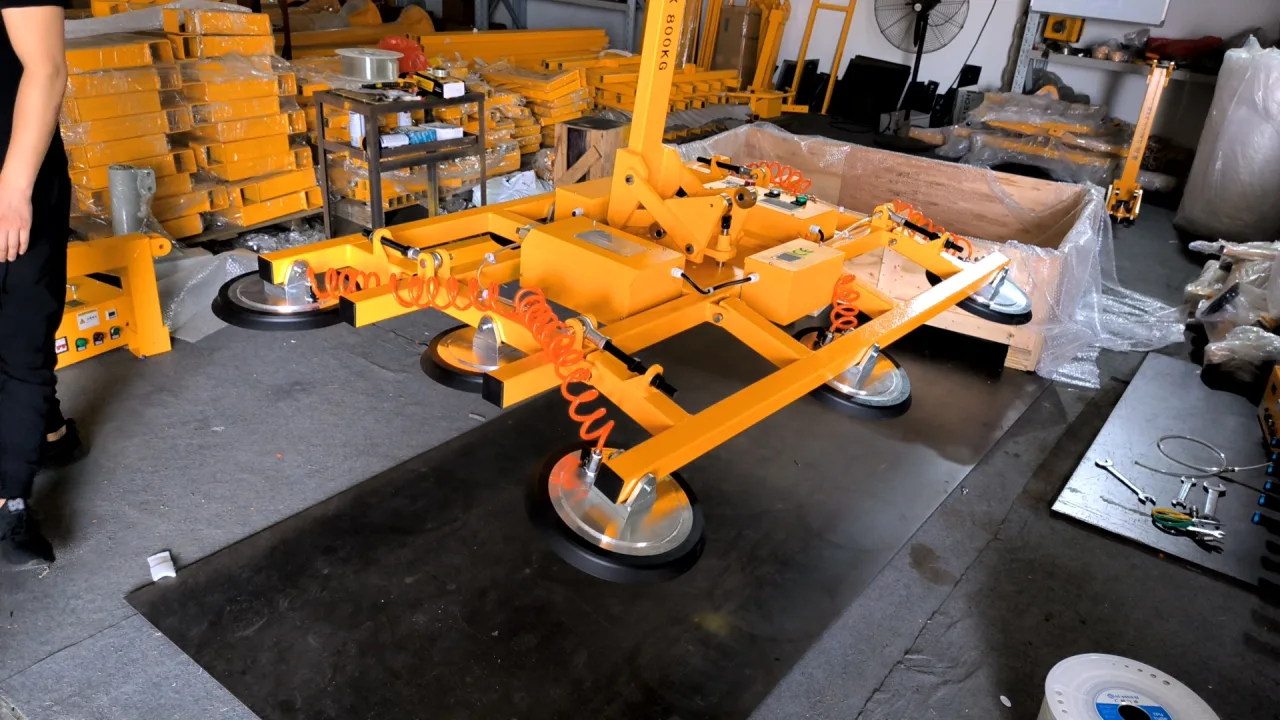
This Singapore project called for an 800 kg vacuum lifter for curved glass that could also work with flat glass. The custom ETJSB-G800 configuration combines eight 300 mm suction pads, an adjustable pad arrangement, battery-powered vacuum, manual 90° tilting and manual 360° rotation. The photographs show the assembled equipment at the factory, including its upright position under a hoist.
The useful starting point is the shape of the pane and the position in which it must be handled. Capacity, pad contact and movement clearance all have to work together.
How the pad arrangement accommodates curvature
The end-view design drawing below shows the outer pad groups angled relative to the central pads. This is the important difference from a fixed, coplanar pad frame: the contact positions can follow the curved surface instead of requiring every pad to face the same plane.
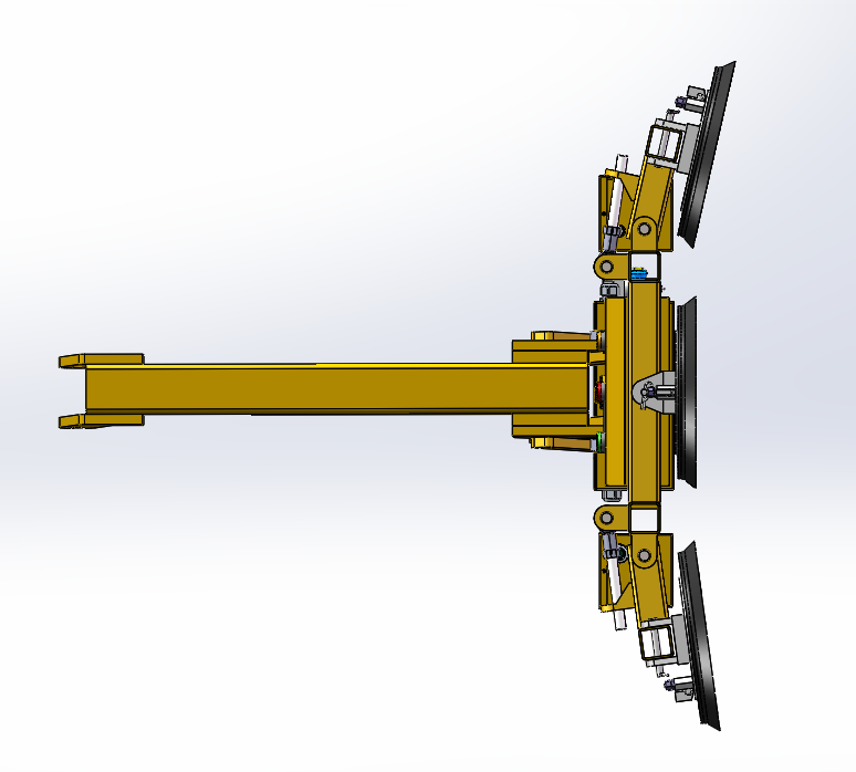
Each pad needs a suitable contact area on the glass. Being close to the surface is not enough if a sealing lip sits across an edge, a surface feature or an angle it cannot accommodate. For another curved-glass project, the glass cross-section and the intended gripping face are therefore as important as the weight.
Adjustability also has a practical limit: it is a way to match an agreed range of glass shapes, not a universal fit for every radius. A radius drawing should be reviewed together with pane dimensions, glass construction and pad positions before a configuration is selected.
Using the same frame for flat glass
The project specification also includes flat-glass handling. In the flat arrangement shown below, the pad faces lie in a common plane. The same equipment concept can therefore serve two glass-shape requirements without treating a curved pane as though it were flat.
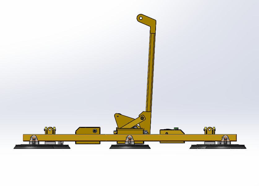
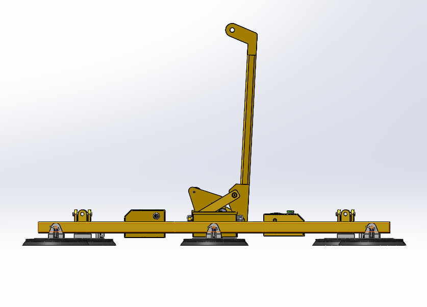
Changing from curved to flat work is a configuration change. Follow the machine's setup instructions with the equipment unloaded and the load safely supported, then check pad alignment and the contact arrangement for the next pane.
A useful purchasing question is whether your smallest and largest panes can both accommodate the required pad layout. A smaller, lighter pane can be the more difficult fit if its usable gripping area is limited.
Why eight pads do not mean “100 kg per pad”
The assembly uses eight pads of 300 mm diameter. The perspective drawing makes their distribution easier to see than a single capacity figure does: the pads are spread around the frame, including the central positions and outer groups.
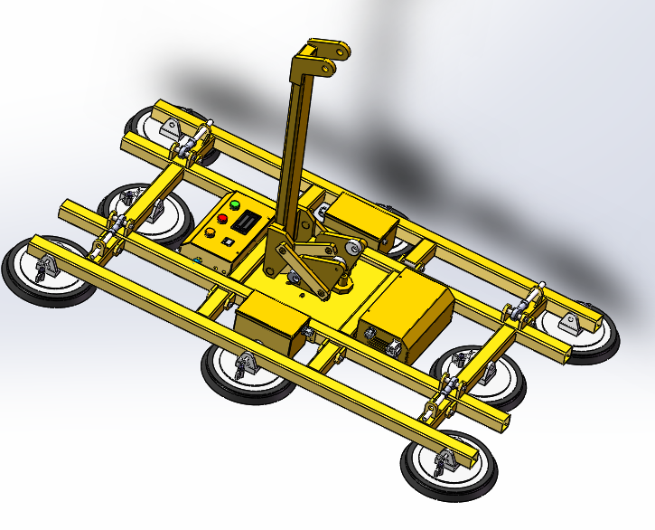
The 800 kg rating belongs to the configured lifting assembly. Dividing it by eight does not create an independent 100 kg rating for each pad, and removing pads does not produce an approved lower-capacity version. Glass shape, load distribution, pad contact and the complete vacuum system remain part of the selection.
For curved glass, the important comparison is not simply “more pads versus fewer pads.” It is whether the pad positions fit the pane and maintain the intended support arrangement throughout the required movement.
Tilting and rotation solve different positioning problems
Movement | Purpose and clearance check |
|---|---|
90° manual tilting | Changes the gripping frame from horizontal to vertical. Check space beneath and around the pane throughout the tilt, including the pickup and delivery positions. |
360° manual rotation | Changes the pane's orientation within the gripping plane. Check the sweep of its edges near racks, walls, other equipment and the operator's working area. |
Crane or hoist travel | Raises and moves the suspended assembly. Check the complete suspended load, available hook height and travel route. |
Neither manual function is a powered positioning drive. Battery power operates the vacuum system; it does not turn this suspended lifter into a self-propelled glass robot. The hoist, its support and the handling route must be selected for the complete task.
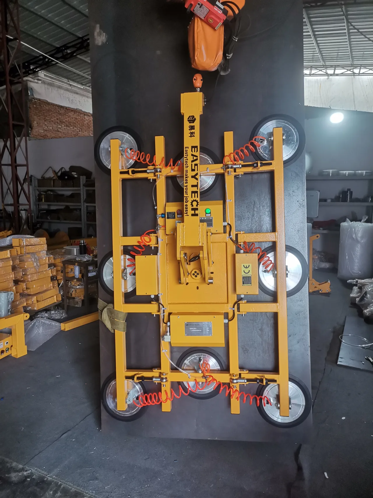
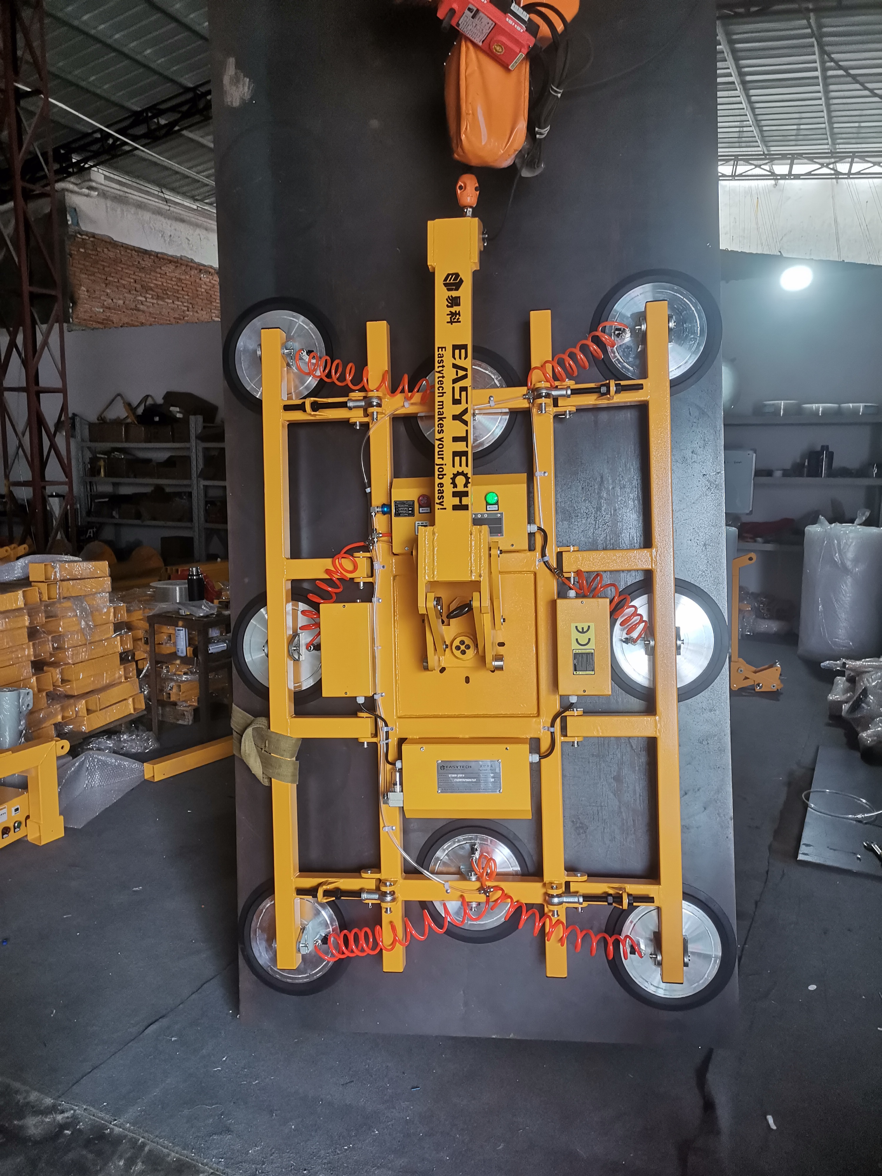
The upright factory photograph is particularly useful for planning: the hook connection, lifting arm, frame and pane all occupy space. Checking only the glass height leaves out part of the required lifting envelope. Use an installation layout to assess the full assembly and its movement.
Battery vacuum and controls on the frame
The project includes battery-powered vacuum and a sound-and-light alarm. The factory detail photograph shows the control enclosure, vacuum hoses and pad-support hardware on the assembled frame. These are parts the operator must be able to inspect and access in the intended working position.
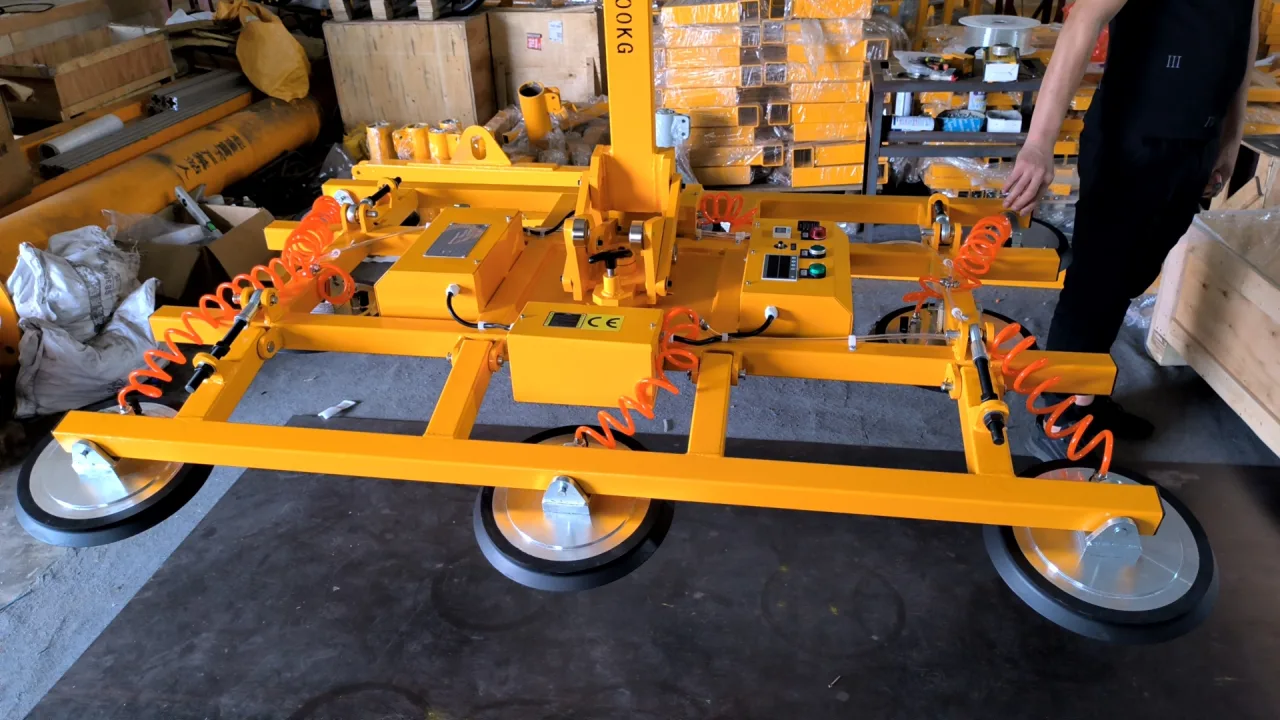
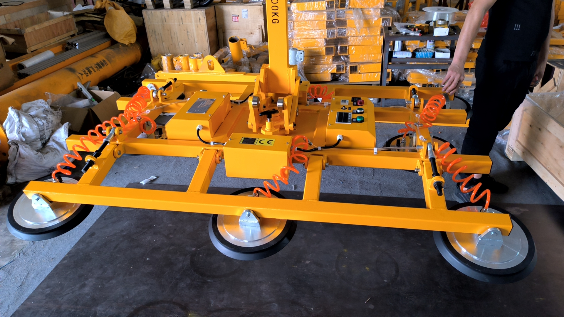
For daily planning, separate battery readiness from lifting capability. The correct charger, charging arrangements and the machine's pre-use checks matter alongside the glass-handling setup. Battery power alone does not establish an outdoor weather rating or permission to work in wind.
If the alarm activates or the vacuum cannot be maintained, follow the supplied operating procedure and keep people clear of the suspended load. An alarm is a reason to respond, not an extra capacity margin.
Factory checks before dispatch
The pre-delivery checklist for this unit was marked PASS on 12 June 2023. Its checks covered the frame and fasteners, suction-pad lips, hoses and connections, control operation, vacuum indication and leakage, lifting checks, and load retention after loss of supply. Packaging and accompanying items were also checked before dispatch.
For a buyer, the important connection is between the agreed glass-handling configuration and the equipment being checked. Before workplace use, the crane, access, glass condition and handling route also need to be assessed for that configuration.
What to prepare for a similar glass-handling project
Information to send | Decision it helps resolve |
|---|---|
A drawing of each curved cross-section, with radius or chord and rise, plus the face to be gripped | Whether the pad angles and positions can match the glass |
Minimum and maximum pane size, weight and thickness; glass construction | The capacity requirement, usable pad area and support arrangement |
Photos of coatings, films, surface features and edges in the proposed contact areas | Which areas are available for suitable pad contact |
Pickup and delivery positions, including the required tilt or rotation | Which movements are needed and where clearance is tight |
Hoist information and a dimensioned view of the handling route | How the complete suspended assembly fits the workplace |
The flat panes that will share the lifter | Whether both shape requirements can be covered by the proposed arrangement |
If a radius drawing is not available, start with photographs and the dimensions you do know. Identify the missing geometry before equipment selection; do not estimate a safe lifting configuration from a photograph alone.
Questions this project answers
Can one vacuum lifter handle both curved and flat glass?
Yes. This custom configuration was specified for both, using an adjustable pad arrangement. The glass shapes and contact layout still need to be matched to the equipment; the capability does not make every curved pane suitable.
How should an equivalent unit be specified?
Specify the custom project configuration, including the eight 300 mm pads, required glass shapes and movements. Use the agreed project drawing to identify the arrangement: the model name ETJSB-G800 alone does not describe every configuration detail.
Should I choose by weight or curvature first?
Provide both at the start. Weight sets a capacity requirement; curvature and the gripping face determine whether the pad arrangement can fit. Then check pane support, the required movements and the available lifting space together.
For the next step, explore curved-glass handling requirements, compare the wider glass vacuum lifter range, or send your glass drawings and workplace photographs for a configuration discussion.