Show the actual panel cross-section
Provide the panel manufacturer’s cross-section, length, width, weight and face material. Identify ribs, seams, protective film and any surface area that cannot be contacted. A nominal panel width does not describe the area available for a suction pad.
Panel feature | Question to resolve |
|---|---|
Smooth or micro-ribbed face | Can the specified pad seat and maintain the required contact? |
Deep ribs or corrugations | Which areas can the approved sealing arrangement actually engage? |
Protective film | Is lifting through the film permitted for this exact arrangement? |
Long flexible panel | Where must support be placed to control deflection and contact? |
Edge joint or tongue | Will the frame or pads obstruct final insertion and release? |
Plan pickup, turning and final approach separately
A panel may leave the stack horizontally and finish on a wall or roof. Show the entire change of orientation, the crane approach, roof pitch or wall position, and the final placement clearance. Specify any required tilt or rotation explicitly.
ET-CL-ROOF-1000 lists 1,000 kg horizontal and 500 kg vertical at the stated 60% vacuum condition. Match the contact arrangement, panel construction and installation sequence to the actual orientation; these values do not establish a universal profile, panel-length or environmental limit.
Check the installation environment
Include access, overhead obstructions, support equipment and the conditions expected on site. Wind and large panel area can affect the lift independently of weight. Use the equipment’s documented operating limits and the project lifting plan; a generic outdoor description is not an operating approval.
What to include in the enquiry
- Panel drawing and photographs of both faces and the edge profile.
- Largest and smallest panel dimensions, weights and relevant surface variations.
- Stacking arrangement and final roof/wall position.
- Required movements and a sketch of the crane or host-machine approach.
- Supply scope for lifting equipment, pad arrangement, controls and documents.
Worked selection check: a panel that turns upright
Model / configuration | Horizontal handling load | Vertical handling load | Load conditions | Pad dimensions |
|---|---|---|---|---|
1000 kg | 500 kg | 60% vacuum level | 120 × 520 mm |
For a hypothetical 700 kg panel, the 1,000 kg horizontal figure alone is insufficient if the operation requires vertical handling. ET-CL-ROOF-1000 lists only 500 kg vertically at the stated condition, so that vertical task is outside the published load value. A different approved configuration would be needed. This is an arithmetic screening example, not approval of horizontal handling for that panel.
Three drawings make the review more useful
- Panel section: rib geometry, facing/core construction and allowed contact zones.
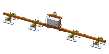
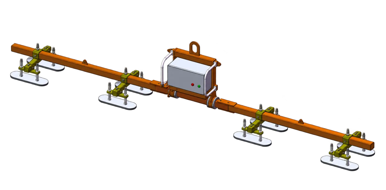
- Lifting layout: pad positions, support locations and any extension beams.
- Installation section: roof pitch or facade setback, hook approach and withdrawal after fastening.
The equipment frame size does not establish a maximum panel length. Obtain the panel handling requirements and the configuration-specific environmental limits rather than borrowing a length or wind figure from another lifter.
Continue your equipment review
Cladding vacuum lifter configuration · Cladding installation application · Installation document requests
Questions for this equipment decision
Which panel and site details affect the quotation?
Panel geometry, pad arrangement, frame length, tilt requirements, vacuum supply and site delivery determine the quotation.
How are smooth, ribbed and corrugated sandwich panels assessed for vacuum lifting?
Send the panel cross-section, rib spacing, coating, surface condition, length and weight. The suction-pad contact pattern must match the actual profile and avoid unsuitable contact areas. Smooth, ribbed and corrugated panels should be assessed separately with the intended handling orientation.
How do roof and wall installation directions affect the lifting configuration?
Describe both the panel’s orientation during lifting and whether it will be installed on a roof or a wall. These are separate requirements. Check the frame layout, permitted lifting direction and any required tilt movement against the actual model specifications. Do not apply one maximum capacity to every orientation.
What information is required for handling long panels outdoors?
Provide panel length, weight, support spacing, storage position, lifting route and crane arrangement. Describe the site exposure and anticipated environmental conditions. Use the operating limits for the exact lifting configuration, including its wind and stop-work requirements. Panel area and handling posture matter as well as weight.
What determines a cladding vacuum lifter quotation?
Include the panel profile drawing, length and weight range, required handling orientations, roof or wall installation method, lifting support and available power source. State the delivery destination and required documents. These details define the frame, pads, movements and supply scope used to prepare the quotation.